Section06ELECTRICALSYSTEM
Subsection 02 (CHARGING SYSTEM)
529 035 868
RECTIFIER/REGULATOR
Continuity Test
Due to internal circuitry, there is no static test avail-
able to check continuity.
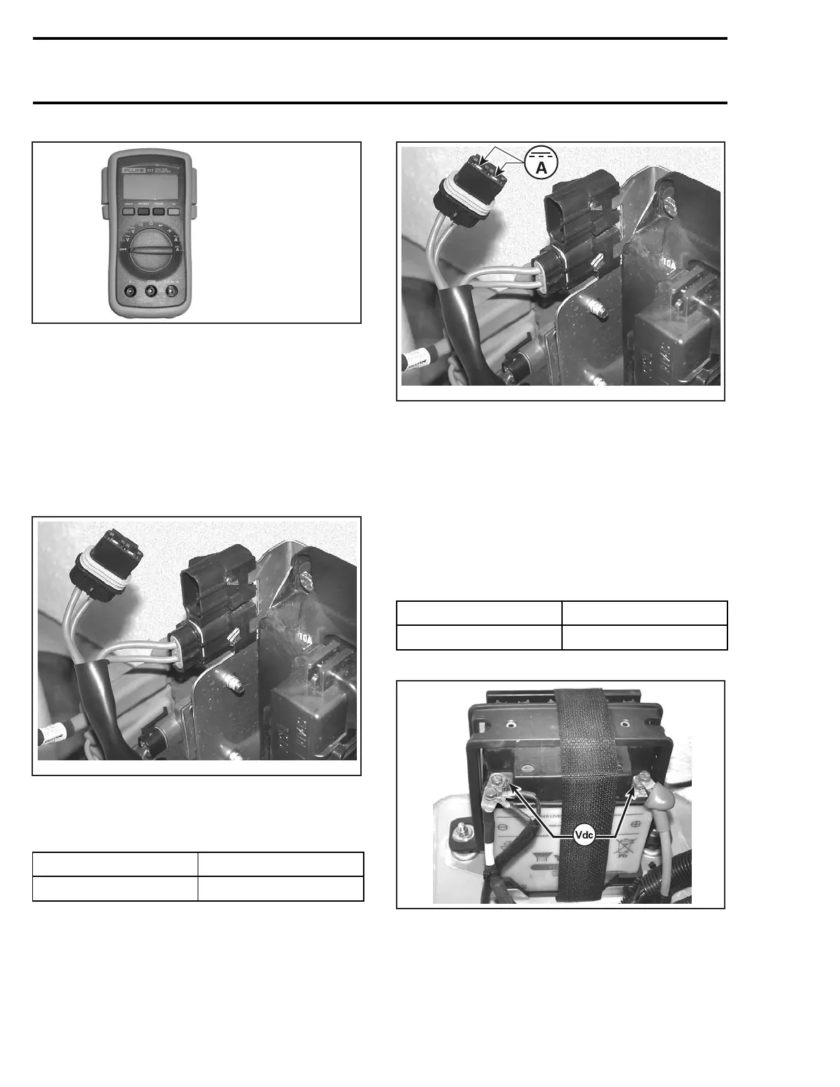
DC Current Test
Proceed as follows:
– Remove charging system fuse.
F18H1TA
– Connect probes to fuse holder terminals.
– Set multimeter to Adc.
– Start engine.
TEST ENGINE SPEED CURRENT
6000 RPM min. 5 A
– Read current.
F18H1TB
– If current is below specification, check magneto
(stator) output prior to concluding that rectifier
is faulty.
– Reinstall fuse.
DC Voltage Test
Proceed as follows:
– Set multimeter to Vdc scale.
– Connect multimeter to battery posts.
– Start engine.
TEST ENGINE SPEED VOLTAGE
5500 RPM Max. 15 Vdc
– Read voltage.
F18H1SA
– If voltage is above specification, replace rectifi-
er/regulator.
154 smr2005-016

 Loading...


