Section 08 STEERING SYSTEM
Subsection 01 (STEERING SYSTEM)
Steering Cable
Disconnect steering cable no. 43 from steering
stem arm no. 33.
Remove retaining block no. 29.
Disconnect ball joint no. 44 from jet pump nozzle.
Remove ball joint and jam nut no. 45 from cable.
Loosen nut no. 46, then remove half rings no. 47
and O-ring no. 48.
NOTE: To loosen nut, use the steering cable tool
(P/N 295 000 145).
Remove steering cable from watercraft.
ASSEMBLY
Assembly is essentially the reverse of disassem-
bly procedures. However, pay particular attention
to the following.
CAUTION: Apply all specified torques and ser-
vice products as per main illustration at the be-
ginning of this subsection.
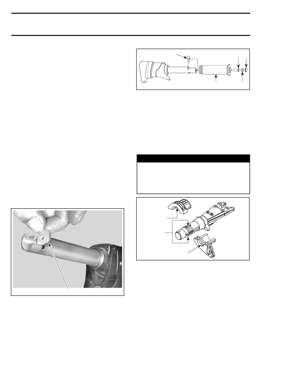
Handle Grip and Grip Insert
When installing the grip insert no. 8 in the handle-
bar no. 9, ensure that it is properly inserted in the
slot at the end of the handlebar tubing.
F02K0JA
1
1. Grip insert
Install grip no. 5 on handlebar no. 9 matching it to
the notch in the handlebar.
Install flat washer and screw no. 7.
Torque screw to 7 N•m(62lbf•in).
Install cap no. 6.
F02K0KA
1
2
4
53
1. Grip insert
2. Grip
3. Flat washer
4. Screw
5. Cap
CAUTION: Ensure to install flat washer other-
wise screw will damage grip end.
Steering Stem
Position steering stem arm no. 33 and support
no. 37 onto steering stem no. 38.
WARNING
Make sure the integrated flat keys of the steer-
ing stem arm and support are properly seat-
ed in steering stem keyways. Steering stem
arm must be locked in place before torquing
the bolts.
F07K09A
2
1
2
1. Keyways
2. Integrated flat key
Replace lock nuts no. 49 by new ones.
Torque bolts no. 36 of steering stem arm to 6 N•m
(53 lbf•in).
Handlebar Support
GTX Supercharged Limited Models Only
Apply Loctite antiseize lubricant (P/N 293 800 070)
then install support bushings no. 50 on handlebar
support.
234 smr2005-022
 Loading...


