Section 08 STEERING SYSTEM
Subsection 02 (OFF-POWER ASSISTED STEERING SYSTEM (O.P.A.S.))
1
F18K0MA
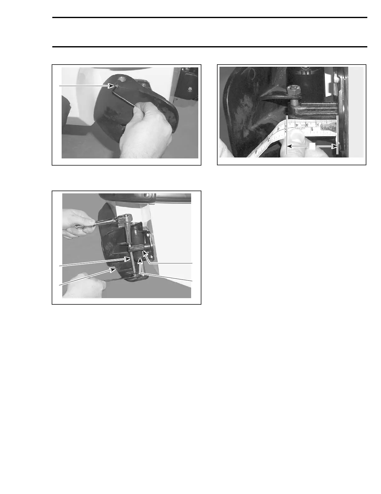
1. Socket screw
Remove the tie-rod screw no. 3.
1
2
F18K0LA
4
3
1. Tie rod screw
2. Side vane
3. Cylinder support
4. Tie rod fitting
Lift pivot shaft no. 4 while holding top of side vane.
Pull side vane out.
Adjustment
During tie-rod fitting adjustment, tie-rod screw
no. 3 must be loose and socket screw no. 2
removed.
Put the steering in straight ahead position.
Measure the portion of tie rod fitting no. 5 exceed-
ing from cylinder support no. 6.
The exceeding distance of tie rod fitting from the
cylinder support should be 45 ± 1 mm (1.65 ±
.04 in).
A
F18K0ZA
A. 45 ± 1 mm (1.65 ± .04 in)
To adjust the tie-rod fitting no. 5, remove tie-rod
screw no. 3 and turn tie-rod fitting. Place tie-rod
screw in its place and measure again. Repeat the
procedure until the distance is reached.
When the adjustment is done, torque the tie-rod
screw to 4.5 N•m(40lbf•in).
Install socket screw no. 2 andtorqueitto2.7N•m
(24 lbf•in).
NOTE: The socket screw no. 2 should be turned
2–3 turns before using a tool.
Installation
Installation is the reverse process of removal.
Install the tie-rod screw no. 3. Do not torque yet.
Perform the tie-rod fitting adjustment. See above.
CYLINDER SUPPORT
Removal
Removal procedure for RH and LH cylinder sup-
port assembly is same.
Remove side vane as mentioned above.
NOTE: To disassemble the cylinder, it is not re-
quired to remove it from vehicle. See DISASSEM-
BLY procedure.
Unscrew tie rod fitting no. 5 from tie rod no. 7.
Unscrew 4 socket screws no. 8. Discard them.
smr2005-039 243