Section07PROPULSION
Subsection 02 (DRIVE SYSTEM)
F01I0FA
321
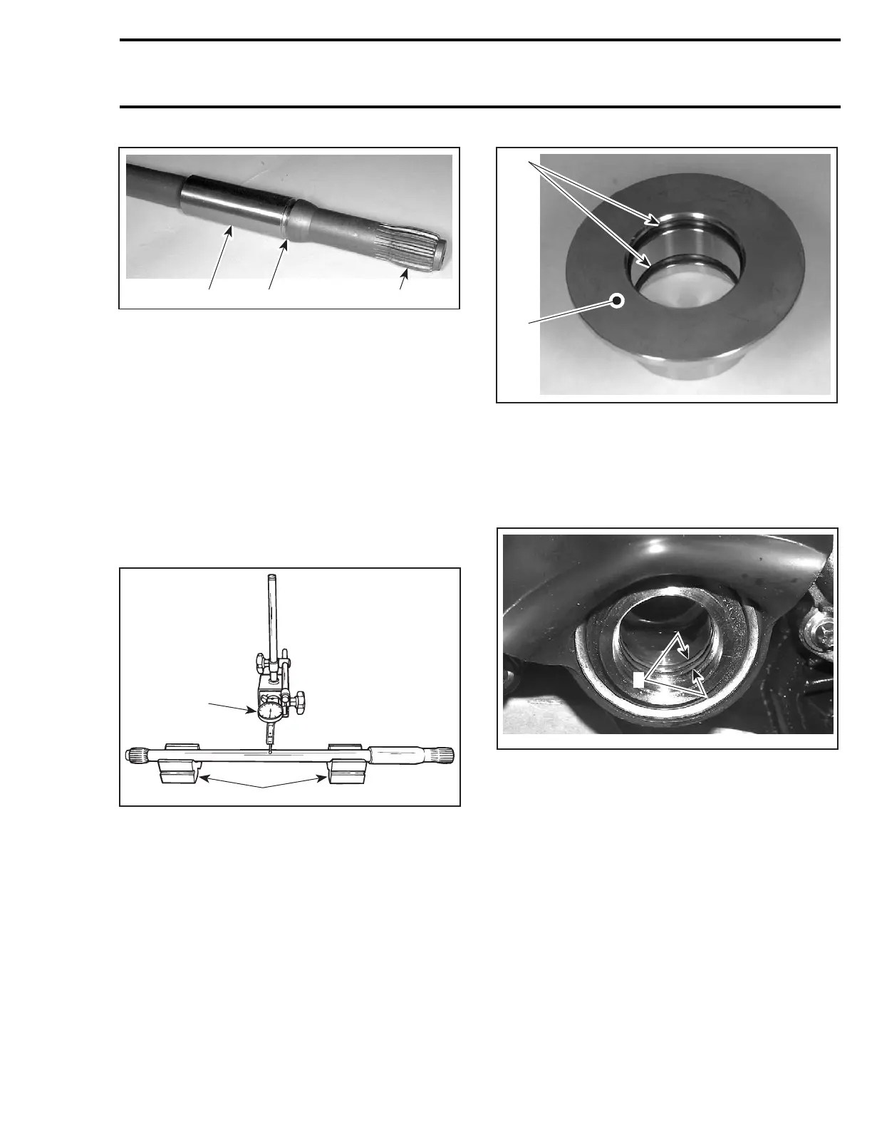
TYPICAL
1. Surface condition
2. Groove condition
3. Splines condition
Excessive deflection could cause vibration and
damage to drive shaft splines, impeller, flywheel
or floating ring.
Place drive shaft on V-blocks and set-up a dial
gauge in center of shaft. Slowly rotate shaft; dif-
ference between highest and lowest dial gauge
reading is deflection. Refer to the following illus-
tration.
Maximum permissible deflection is 0.5 mm
(.020 in).
1
2
F01J15A
MEASURING DRIVE SHAFT DEFLECTION
1. Dial gauge
2. V-blocks
Damper
4-TEC Models
Discard damper no. 8 to install a new one.
Floating Ring and O-Ring
Inspect condition of O-rings no. 9 and floating ring
contact surface.
F01I0GA
1
2
1. O-rings
2. Floating ring contact surface
PTO Seal
Discard both O-rings no. 10 inside PTO seal and
install new ones.
F18C01A
1
1. O-rings
Inspect PTO seal assembly. Refer to PTO
HOUSING/MAGNETO section.
Boot
Inspect the condition of boot. If there is any dam-
age or evidence of wear, replace it.
INSTALLATION
Installation is essentially the reverse of removal
procedure. However, pay particular attention to
the following.
smr2005-020 209
 Loading...


