Section 07 PROPULSION
Subsection 02 (DRIVE SYSTEM)
Drive Shaft
NOTE: Ensure to install floating ring no. 1 before
inserting the drive shaft no. 3 in PTO seal assem-
bly.
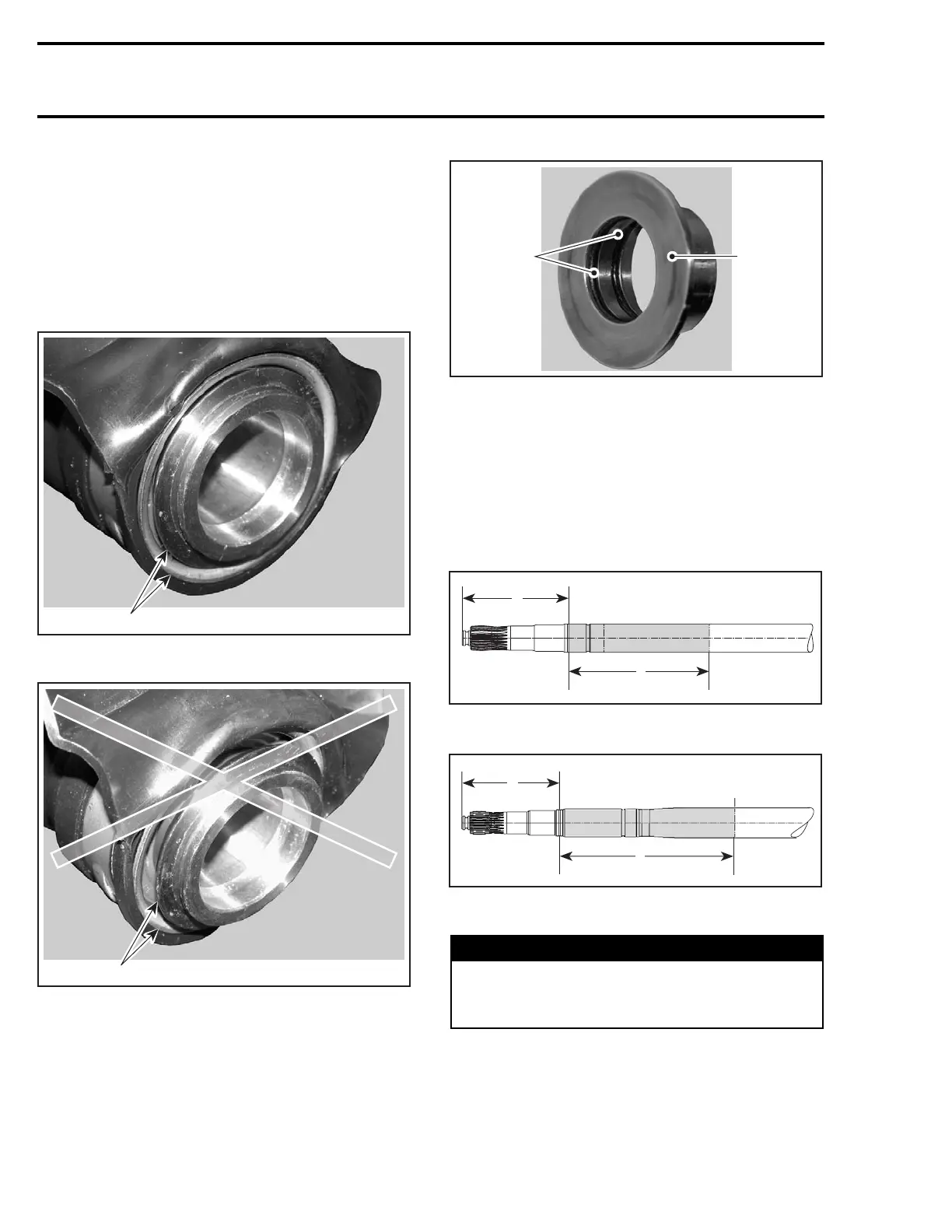
Before installing drive shaft, inspect PTO seal as-
sembly. The inner sleeve must be flush with outer
circumference of the assembly. Otherwise, gen-
tly push or tap on inner sleeve until flush.
F18I0EA
1
CORRECT INSTALLATION
1. Inner sleeve flush with outer circumference
F18I0FA
1
WRONG INSTALLATION
1. Inner sleeve not flush with outer circumference
Apply a thin coat of synthetic grease (P/N 293 550
010) on the floating ring O-rings no. 9. Do not get
grease on floating ring sealing surface.
1
F18I0KA
2
1. Synthetic grease
2. No lubrication
To prevent possible drive shaft corrosion, apply
anti-corrosion spray (P/N 219 700 304) on drive
shaft where shown.
NOTE: Drive shaft should be dry and clean prior
to applying the corrosion protectant. If the drive
shaft is corroded, a rotating wire brush may be
used.
A
F18J25A
B
A. 89 mm (3.3 in)
B. 131 mm (5.2 in) — zone to apply primer
F19J0BA
A
B
A. 101mm(4in)
B. 180 mm (7.1 in) — zone to apply primer
WARNING
Always work in a well ventilated area. Care-
fully read application instructions on product
can.
Wait 2 hours prior to using the watercraft to allow
protectant to dry.
210 smr2005-020

 Loading...


