Section 07 PROPULSION
Subsection 04 (VARIABLE TRIM SYSTEM)
INSPECTION
Rubber Boot
Make sure rubber boot no. 3 is in good condition.
If it is cracked or torn, replace boot.
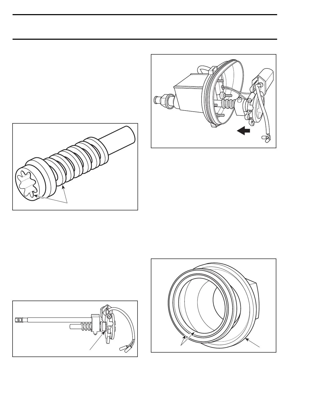
Worm
Inspect threads and splines of worm no. 9 for
wear. If worm replacement is necessary, renew
also sliding shaft.
F01J25A
1
1. Inspect threads and splines
ASSEMBLY
Assembly is essentially the reverse of disassem-
bly procedures. However pay particular attention
to the following.
Motor, Worm and Sliding Shaft
Apply synthetic grease (P/N 293 550 010) to
worm.
Screw worm no. 9 to sliding shaft no. 10.
Mesh worm splines to gear of motor.
F01J2PA
1
1. Mesh worm spline to gear of motor
Install motor no. 8, worm and sliding shaft in VTS
housing.
F01J2GA
Tighten nuts no. 11 to7N•m(62lbf•in).
Connect wires of motor.
CAUTION: Make sure wire color codes match.
Install cover no. 7.
NOTE: Make sure seal no. 12 is in place.
INSTALLATION
Installation is essentially the reverse of removal
procedures. However pay particular attention to
the following.
Nut and Sealing Washer
Place sealing washer no. 5 on nut no. 4. Make
sure seal lips are facing toward hull.
F01J2LA
1
2
1. Seal lips facing hull
2. Nut
Apply Loctite Primer N (P/N 293 800 041) to
threads of VTS housing, and to nut no. 4.
224 smr2005-028
 Loading...


