Section 08 STEERING SYSTEM
Subsection 02 (OFF-POWER ASSISTED STEERING SYSTEM (O.P.A.S.))
2
F18K0SA
1
1. Phillips screws
2. Rod grommet
Pull sealed tube out with tie rod from inside of
bilge towards jet pump side.
1
F18K0TA
2
TYPICAL
1. Sealed tube
2. Tie rod
Remove old silicone sealant around screws holes.
Installation
Installation is the reverse process of removal.
Apply silicone sealant (clear) (P/N 293 800 086) on
the screws before installing and, inside the hull,
around screw holes after torquing.
Torque Phillips screws no. 26 to 2.2 N•m
(19 lbf•in).
FILTER
GTX Series, Wake and RXT Models
For removal and installation procedure, refer to
JET PUMP.
O.P.A.S. filter is part of plastic elbow no. 28.
Check for cleanness. Replace or clean it as nec-
essary.
VALVE
GTX Series, Wake and RXT Models
Removal
Remove O.P.A.S. “U” lever screw no. 17,flat
washer no. 18, bushing no. 19 and venturi bush-
ing no. 20 from nozzle.
Remove jet pump, filter and formed hose no. 29
(refer to JET PUMP).
Remove gear clamps no. 30 to remove water
hoses no. 31 from valve.
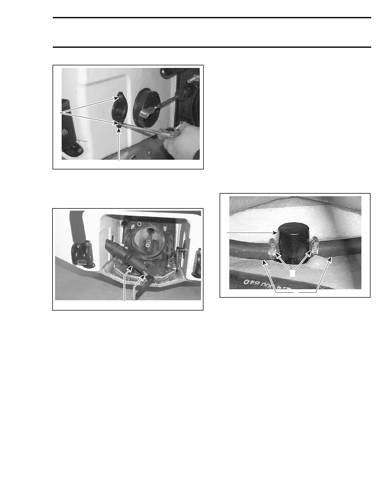
F18K0UA
3
2
1
1. Gear clamps
2. Valve
3. Water hoses
If the disassembly of valve is necessary, loosen
bottom nut of valve no. 32 using the O.P.A.S. cylin-
der nut wrench (P/N 529 035 840).
smr2005-039 247