Section 08 STEERING SYSTEM
Subsection 02 (OFF-POWER ASSISTED STEERING SYSTEM (O.P.A.S.))
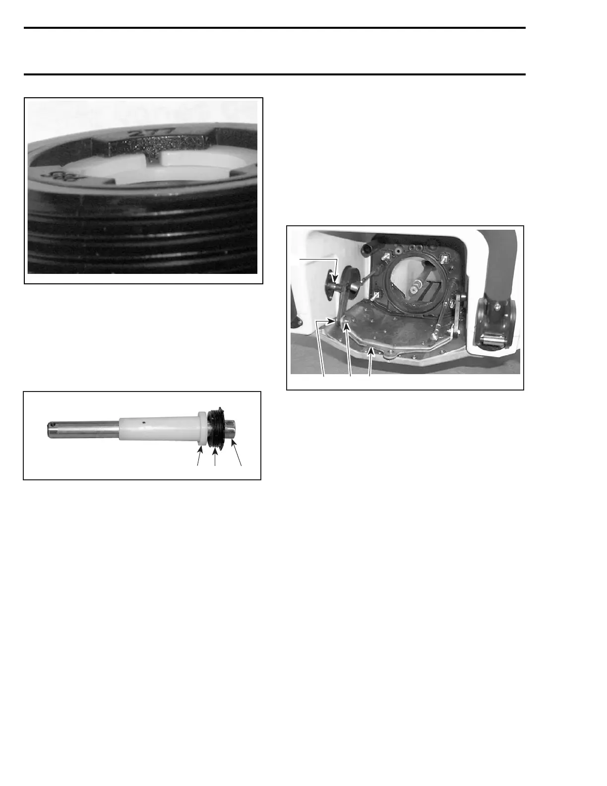
smr05-039-007
UPPER SPLIT RING
Install removed parts in the cylinder.
Using the O.P.A.S. cylinder nut wrench (P/N 529
035 840) torque the cylinder cap to 7 N•m
(62 lbf•in). After tightening, keep turning the cap
until the locking tab goes over the stopper.
RXT Models
1
F19J0DA
2
3
1. Pivot rod
2. Spacer
3. Cylinder cap assembly
The cylinder disassembly is not necessary for
these models.
Check pivot rod no. 4 for cracks or scratches. Re-
place pivot rod, if necessary.
Installation
The installation is the reverse of the removal pro-
cedure. However, pay attention to the following
detail.
Perform the tie-rod fitting adjustment. See above.
TIE ROD
Removal
Removal procedure for RH and LH tie rod no. 7 is
same.
Remove side vane no. 1 and cylinder support no. 6
as mentioned above.
Remove O.P.A.S. “U” lever screw no. 17,flat
washer no. 18, bushing no. 19 and venturi bush-
ing no. 20 from nozzle.
Removejetpump(refertoJETPUMP).
Remove screw no. 21 and washers no. 22 to re-
move “U” lever no. 23 from tie rod connecting
levers no. 24.
2
F18K0RA
13
4
TYPICAL
1. “U” lever screw
2. Screw
3. Tie rod connecting lever
4. Tie rod
Pull tie rod out from jet pump side with the sealed
tube no. 25.
Unscrew lever from the tie rod.
Installation
Installation is the reverse process of removal.
Torque screw no. 21 to 7 N•m(62lbf•in).
Torque O.P.A.S. “U” lever screw no. 17 to 20 N•m
(15 lbf•ft).
SEALED TUBE
Removal
Removal procedure for RH and LH sealed tube
no. 25 is same.
Remove side van no. 1, cylinder housing no. 6 and
O.P.A.S. “U” lever no. 23 as mentioned above.
Removejetpump(refertoJETPUMP).
Remove Phillips screws no. 26 and remove rod
grommet no. 27.
246 smr2005-039
 Loading...


