Section 09 HULL/BODY
Subsection 01 (ADJUSTMENT AND REPAIR)
1
2
F18L22A
2
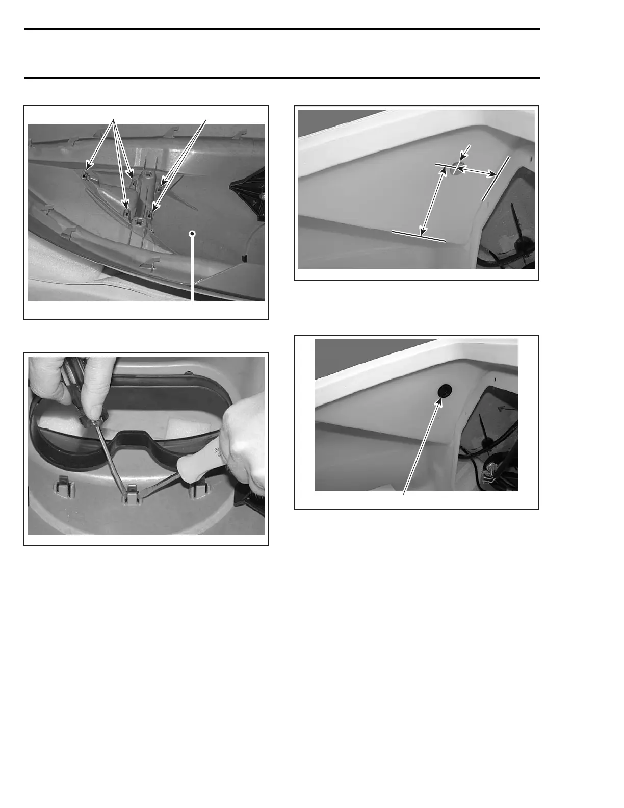
1. Inner skin
2. Deflector retaining clips
F18L23A
RELEASE DEFLECTOR
The installation is the reverse of removal proce-
dure.
SIDE MOLDING
Removal and Installation
All Models except RXT
The removal procedure for RH and LH side mold-
ings with grills is the same.
Remove the two darts holding the grill to the body.
Make a hole into the luggage compartment as
shown in the illustration below to gain access to
the side molding screw.
155 mm
(6.1 in)
F18L29A
55 mm
(2.2 in)
Ø 25 mm
(1 in)
Remove screw and side molding.
After installing side molding, install a plug (P/N 291
000 279) in the side molding screw hole.
1
F18L2AA
1. Plug
GTX Supercharged Limited
Removal procedure for RH and LH side moldings
with deflector/grill is the same.
Side molding is mounted on deflector.
Remove three darts holding deflector and grill.
The installation is the reverse of the removal pro-
cedure.
INLET GRATE
Removal and Installation
Loosen screws and remove inlet grate.
NOTE: An impact screwdriver should be used to
loosen tight screws.
272 smr2005-024
 Loading...


