Section 09 HULL/BODY
Subsection 01 (ADJUSTMENT AND REPAIR)
2
F18L3BA
12
1. Groove
2. Adjustment holes
Align groove with stopper screw, while inserting
the cylinder into housing.
Tighten the stopper screw.
Installation
Before Installation, make sure:
– inside cylinder slides up and down freely with-
out obstruction from grab handle
– safety lock pin operates properly
– stopper screw stops cylinder at its most up-
wards position.
To install the wake post, reverse removal proce-
dure.
SPONSON REPLACEMENT
NOTE: Removal and installation procedure for RH
and LH sponson is same.
Removal
Unscrew sponson bolts then remove sponson.
smr2005-024-014_a
1. Sponson
2. Bolts
Clean any residues of silicone sealant on hull and
sponson.
Installation
Apply silicone sealant (clear) (P/N 293 800 086)
around sponson adaptors.
Apply Loctite 243 (blue) (P/N 293 800 060) on
sponson bolt threads.
Install sponson and torque sponson bolts to 7 N•m
(62 lbf•in).
SPONSON ADAPTOR
NOTE: Removal and installation procedure for RH
and LH sponson adaptor is same.
Removal
Remove appropriate sponson.
Remove muffler or resonator. Refer to EXHAUST
SYSTEM.
Hold sponson adaptors and unscrew sponson
adaptor nuts.
Clean any residues of silicone sealant on hull and
sponson.
Installation
Apply Loctite 243 (blue) (P/N 293 800 060) on
sponson adaptor threads.
Torque sponson adaptor nuts to 16 N•m
(142 lbf•in).
Install all other removed parts.
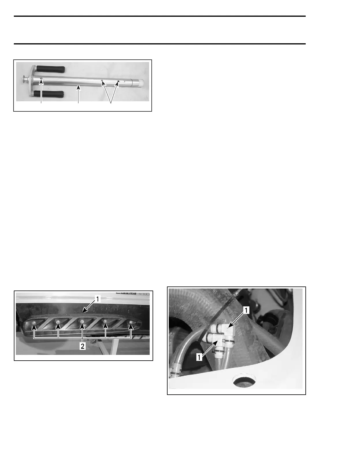
BAILER PICK-UPS INSPECTION
Check if the hole on the elbow fitting is obstruct-
ed. Clean both elbow fittings if necessary.
smr05-005-001_A
1. Elbow fitting holes
278 smr2005-024

 Loading...


