Section 09 HULL/BODY
Subsection 01 (ADJUSTMENT AND REPAIR)
2
F18L1ZA
1
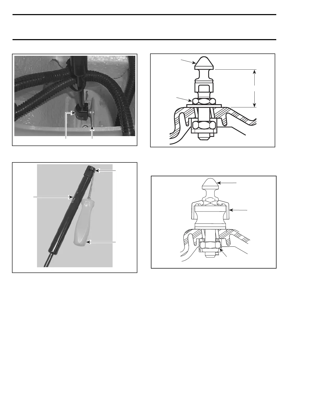
1. Bottom support bracket
2. Shock bottom locking device
1
F18L20A
3
2
1. Shock absorber
2. Flat screwdriver
3. Shock top locking device
The installation is the reverse of the removal pro-
cedure.
STORAGE COMPARTMENT
COVER ADJUSTMENT
NOTE: Apply Loctite 243 (blue) (P/N 293 800 060)
on threads of lock pin when the adjustment is re-
quired or when the lock pin is removed then rein-
stalled. The threads on new lock pin are coated
with a self-locking product, do not apply Loctite
243onthreads.
Adjust lock pin as per following specifications:
F06L04A
A
2
1
FIXED TYPE LOCK PIN
1. Lock pin (apply Loctite 243 on threads)
2. Adjustment nut. Torque to 5 N•m(44lbf•
in)
A. 30 ± 1 mm (1-3/16 ± 3/64 in)
2
1
3
smr2005-024-008_a
FLOATING TYPE
1. Lock pin (apply Loctite 243 on threads)
2. Rubber cushion pad
3. Lock nut. Torque to 5 N•m(44lbf•
in)
NOTE: Some models have a floating type lock pin.
It is normal to have a front and aft play of the rub-
ber cushion pad. To adjust, tighten lock pin until
any vertical play is eliminated. Make sure a front
and aft play remains when pressing by hands.
MIRROR
To remove mirror proceed as follows:
– Remove storage compartment inner shell from
storage cover as described earlier in this sec-
tion.
270 smr2005-024
 Loading...


