Section06ELECTRICALSYSTEM
Subsection 03 (STARTING SYSTEM)
WARNING
Always wear safety glasses when using com-
pressed air.
Remove dirt, oil or grease from commutator using
a clean cloth soaked in suitable solvent. Dry well
using a clean, dry cloth.
Clean engine ring gear teeth and drive unit (clutch).
NOTE: Bushings or bearings must not be cleaned
with grease dissolving agents.
Immerse all metal components in cleaning solu-
tion. Dry using a clean, dry cloth.
STARTER INSPECTION
Armature
NOTE: An ohmmeter may be used for the follow-
ing testing procedures, except for the one con-
cerning shorted windings in armature.
Check commutator for roughness, burnt or scored
surface. If necessary, turn commutator on a lathe,
enough to resurface only.
Check commutator condition with an indicator. If
out of specification, replace the starter.
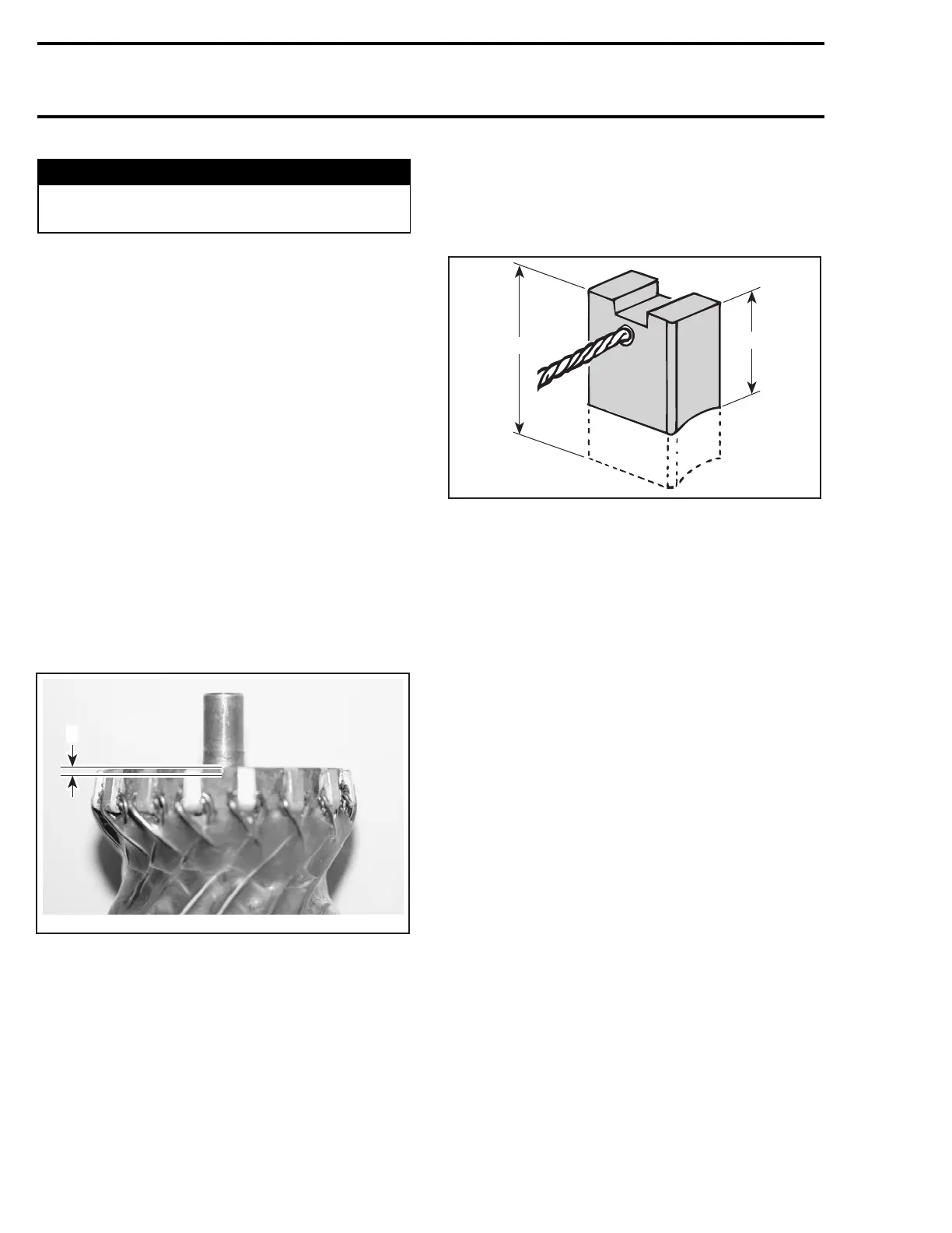
1
F18H0RA
1. Commutator undercut 0.20 mm (.008 in)
Brush Holder
Check brush holder for insulation using an ohm-
meter. Place one test probe on insulated brush
holder and the other test probe on brush holder
plate. If continuity is found, brush holder has to
be repaired or replaced.
Brush
Measure brush length. If less than 8.5 mm
(.335 in), replace them.
NOTE: New brush length is 12 mm (.472 in).
A03E05A
1
2
1. New
2. Wear limit, 8.5 mm (.335 in)
STARTER ASSEMBLY
Reverse the order of disassembly to reassemble
starter.
STARTER INSTALLATION
Installation is essentially the reverse of removal
procedure. However, pay particular attention to
the following.
Make sure that starter and engine mating surfaces
are free of debris. Serious trouble may arise if
starter is not properly aligned.
Apply grease Isoflex Topas NB52 (P/N 293 550
021) on O-rings of starter.
Install starter.
NOTE: If starter does not mesh properly, try to pull
it out and slightly rotate the starter gear; then re-
install starter. One could also temporarily remove
both O-rings, properly mesh gears then remove
starter to reinstall O-rings, being careful not to ro-
tate gear to keep its position, to finally reinstall
starter.
Apply Loctite 243 (P/N 290 897 651) on retaining
screws no. 1 andtorqueto10N•m(89lbf•in).
Connect the RED positive cable to the starter and
torque nut to 7 N•m(62lbf•in). Apply dielectric
grease (P/N 293 550 004) on terminal and nut.
170 smr2005-017

 Loading...


