Section07PROPULSION
Subsection 01 (JET PUMP)
Remove large O-ring no. 37 from pump housing.
Wear Ring
Inspectwearringbeforeremovingit. SeePARTS
INSPECTION further.
Remove the screws no. 38 retaining wear ring
no. 4 in the jet pump housing no. 27.
Place jet pump housing in a vise with soft jaws. It
is best to clamp housing using a lower ear.
Cutwearringattwoplaces.
CAUTION: When cutting ring, be careful not to
damage jet pump housing.
NOTE: Wear ring can be cut using a jigsaw, a small
grinder or a low clearance hacksaw such as Snap-
on HS3 or equivalent.
After cutting ring, insert a screwdriver blade be-
tween jet pump housing and ring outside diame-
ter.
Push ring so that it can collapse internally.
Pull ring out.
CLEANING
Properly clean all threads.
Remove all O-rings and clean parts in a solvent.
Carefully check water passages. Blow low pres-
sure compressed air through them and make sure
they are clear.
1
F18J0XA
1. Water passages
Brush and clean impeller shaft threads, impeller
and drive shaft splines with pulley flange cleaner
(P/N 413 711 809) or equivalent. Free threads and
splines from any residue.
PARTS INSPECTION
Impeller
Visually inspect impeller splines. Check for wear
or deformation. Renew parts if damaged.
NOTE: Check also PTO flywheel and drive shaft
condition. Refer to DRIVE SYSTEM and 1503 EN-
GINE SHOP MANUAL.
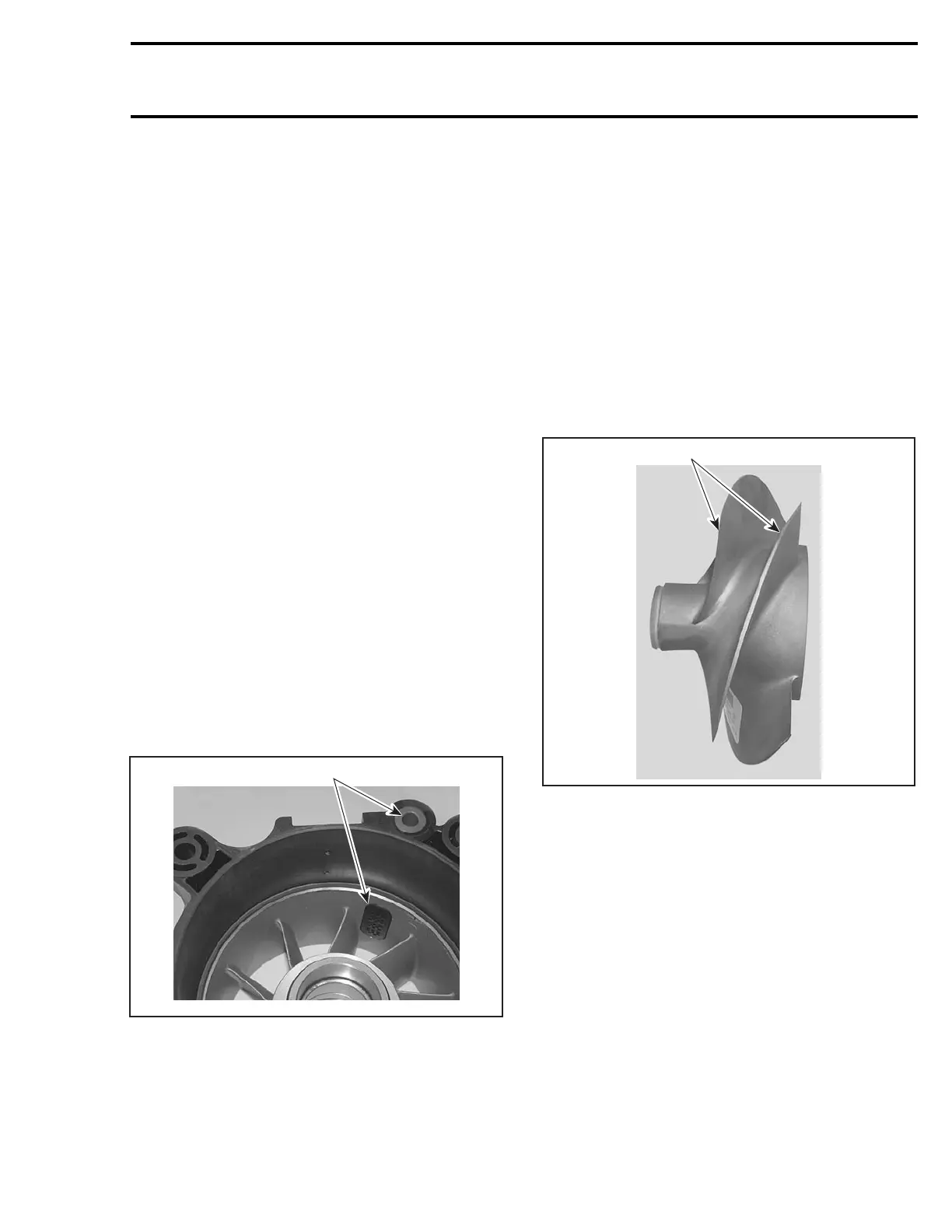
Examine impeller in wear ring for distortion.
Check if blade tips are blunted round, chipped or
broken. Such impeller is unbalanced and will vi-
brate and damage wear ring, impeller shaft, shaft
seal or bearings. Renew if damaged.
1
F18J1BA
1. Replaced if blunted round or damaged
Check impeller for cavitation damage, deep
scratches or any other damage.
smr2005-019 193
 Loading...


