Section07PROPULSION
Subsection 02 (DRIVE SYSTEM)
GENERAL
Jet pump must be removed to replace any com-
ponents of the drive system. Refer to JET PUMP
for removal procedure.
REMOVAL
Drive Shaft
NOTE: When drive shaft will be removed, some
oil will flow out. To prevent it, start engine, run at
4000 RPM for 10 seconds and stop engine at this
RPM. This will move oil out of PTO housing into
oil tank. If engine cannot be started, refer to the
procedure in PTO HOUSING/MAGNETO section
and look for PTO HOUSING REMOVAL.
Remove seat.
RXP Models
Remove engine cover.
All Other Models
Detach coolant expansion reservoir from vent
tube support then move away.
2
F18L1GB
1
TYPICAL
1. Detach expansion reservoir
2. Remove vent tube support
Detach vent tube.
Remove vent tube support.
All Supercharged Models
Remove supercharger. Refer to AIR INTAKE SYS-
TEM in ENGINE SECTION of this shop manual and
to INTAKE MANIFOLD AND SUPERCHARGER of
the 1503 4-TEC ENGINE SHOP MANUAL.
All Models
NOTE: Use this sequence to minimize the amount
of movement the drive shaft will slide back into
PTO seal assembly.
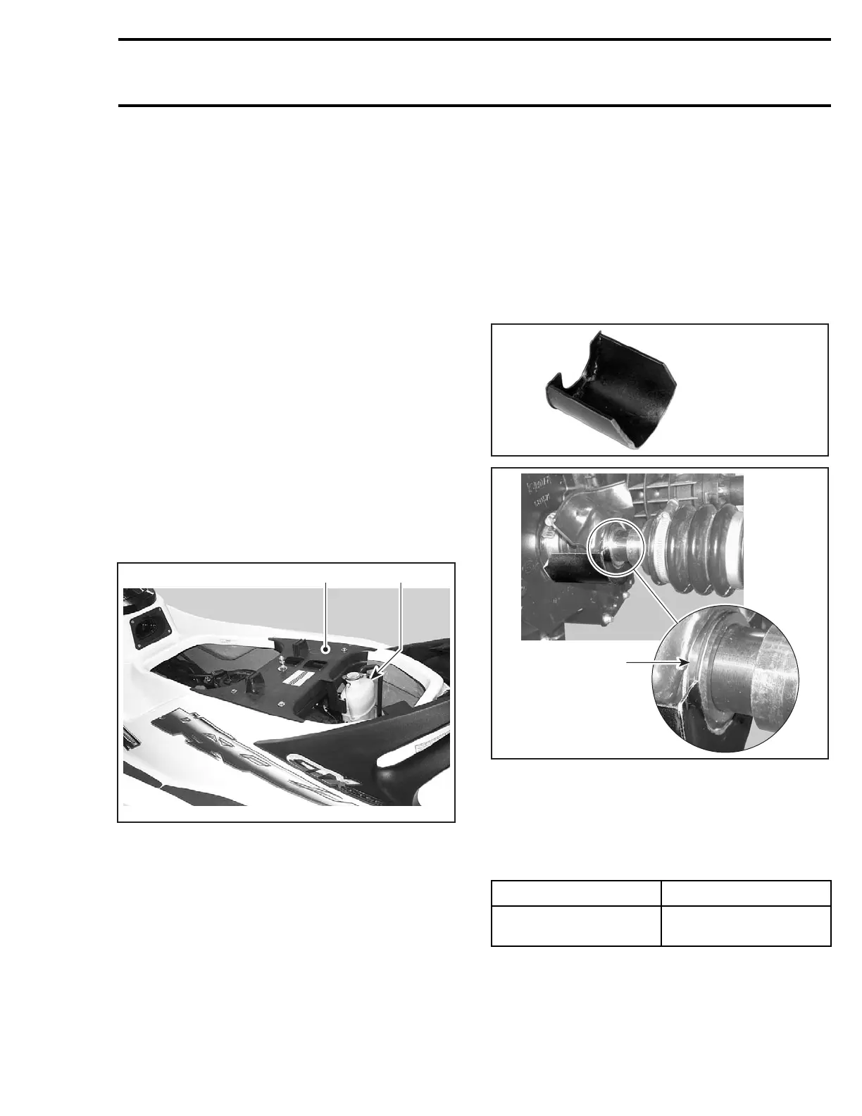
Lift rubber protector to expose PTO seal assem-
bly. Install the PTO seal support tool (P/N 529 035
842) on bottom of PTO seal assembly as shown.
CAUTION: Strictly follow this procedure other-
wise damage to component might occur.
529 035 842
F18I04A
1
1. Insert in groove of PTO seal assembly
Remove jet pump. Refer to JET PUMP section.
Install drive shaft holder on pump support. Refer
to the following table to use the appropriate tool
according to the model.
MODEL TOOL
ALL
Drive shaft holder
(P/N 529 035 986)
NOTE: This is necessary so the drive shaft cannot
move rearwards when using the drive shaft/float-
ing ring tool.
smr2005-020 205
 Loading...


