Section07PROPULSION
Subsection 04 (VARIABLE TRIM SYSTEM)
GENERAL
To test VTS control module, motor or switch, refer
to INSTRUMENTS AND ACCESSORIES.
REMOVAL
Remove seat and engine cover to have access to
VTS module.
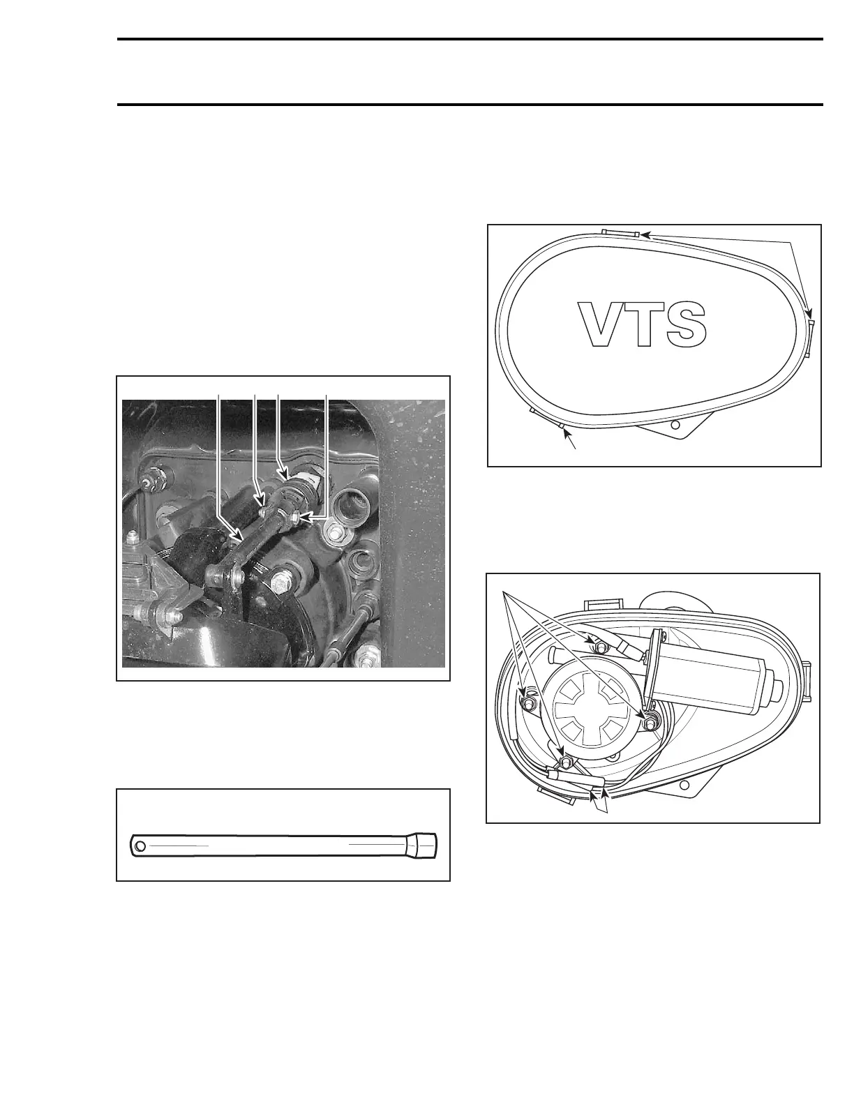
Remove nut no. 14 and bolt no. 13 retaining VTS
rod no. 1 to sliding shaft no. 10.
Remove clamps no. 2.
Remove rubber boot no. 3.
1
F16J0AA
3
4
2
1. VTS rod
2. Bolt
3. Stop nut
4. Rubber boot
To loosen nut no. 4, use the VTS socket tool
(P/N 295 000 133).
295 000 133
Remove sealing washer no. 5.
Disconnect wiring harnesses.
Pull out VTS assembly no. 6 from bilge.
DISASSEMBLY
Cover
Remove VTS cover no. 7 by pressing on tabs.
F01J1WA
1
1
1. Press tabs to remove cover
Motor
Disconnect wires from motor no. 8.
Remove retaining nuts no. 11.
F01J1XA
1
2
1. Remove nuts
2. Disconnect wires
Pull on motor to remove it.
Worm and Sliding Shaft
Simply pull on worm no. 9 and sliding shaft no. 10
in order to remove them.
smr2005-028 223
 Loading...


