Section 03 ENGINE SYSTEM
Subsection 03 (COOLING SYSTEM)
CIRCUIT
The water supply is provided by a pressurized area
in the jet pump between the impeller and venturi.
The water flow is controlled by a reducer located
between the jet pump support and the jet pump
on the inlet side. The reducer is color coded ac-
cording to watercraft model. Refer to JET PUMP.
Water is directed first through the intercooler or
to the exhaust manifold fitting located at front of
manifold for the models without intercooler.
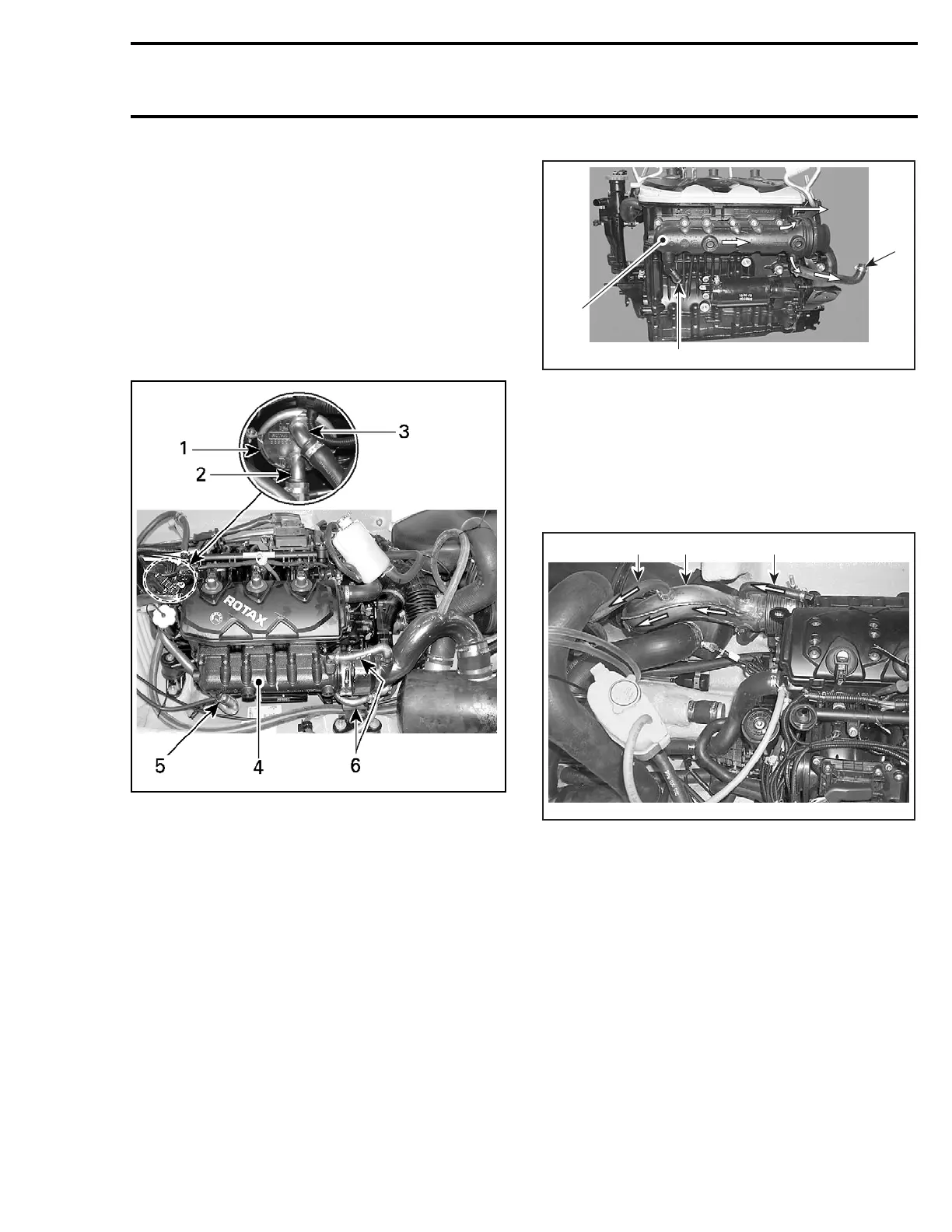
smr2005-008-005_a
TYPICAL — MODELS WITH INTERCOOLER
1. Intercooler
2. Water inlet
3. Toward exhaust manifold
4. Exhaust manifold
5. Water inlet (from intercooler)
6. Water outlet
2
3
F18E1FA
1
TYPICAL — MODELS WITHOUT INTERCOOLER
1. Exhaust manifold
2. Water inlet
3. Water outlet
Water enters the manifold end and is directed to
water jackets of exhaust manifold.
Water exits exhaust manifold through 2 hoses at
rear manifold.
1
F18E1EA
23
TYPICAL
1. Water coming from exhaust manifold
2. Exhaust pipe
3. Bleed hose
Water enters exhaust pipe and flows in the water
jacket of pipe.
smr2005-008 45