Section04ENGINEMANAGEMENT(15034-TEC)
Subsection 03 (COMPONENT INSPECTION, REPLACEMENT AND ADJUSTMENT)
Ensure the throttle body plate stop lever rest
against its stopper. Open throttle approximately
one quarter then quickly release. Repeat 2 -
3 times to settle throttle plate. If stopper does
not rest against its stop lever, perform throttle
cable adjustment. Refer to THROTTLE BODY in
AIR INDUCTION SYSTEM above.
To properly reset valve, first install safety lanyard
then remove it and then wait 5 seconds. Repeat
this cycle 2 - 3 times.
Push the Reset button in the Setting tab of
B.U.D.S.
NOTE: No message will be displayed if operation
is good. If operation is wrong, an error message
will be displayed.
NOTE: There is no idle speed adjustment to
perform. The ECM takes care of that. If TPS is
not within the allowed range while resetting the
CLOSED THROTTLE AND IDLE ACTUATOR,
the ECM will generate a fault code and will not
accept the setting.
Start engine and make sure it operates normally
through its full engine RPM range. If fault codes
appear, refer to SYSTEM FAULT CODES in DIAG-
NOSTIC PROCEDURES section for more informa-
tion.
IDLE BYPASS VALVE
An idle bypass valve with good resistance mea-
surement can still be faulty. It is also possible
that a mechanical failure occurs which is not de-
tectable without measuring the air flow. Replac-
ing the idle bypass valve may be necessary as a
test.
Resistance Test
Disconnect idle bypass valve from the wiring har-
ness.
Using a multimeter, check the resistance in both
windings.
Check the resistance between terminals A and D
andalsobetweenterminalsCandBoftheidle
bypass valve.
The resistance in each winding should be approx-
imately 50 at 23°C(73°F).
If the resistance of one or both windings is not
good, replace the idle bypass valve.
If resistance test of valve windings is good, check
continuity of circuits A-35, A-36, A-37, A-38.
Visual Inspection
Remove idle bypass valve from throttle body.
Check the piston and bypass channel for dirt/
deposits which can cause a sticking piston.
CAUTION: Do not try to operate the piston of
the idle bypass valve when it is dismounted.
Also do not move the piston by hand. The
screw drive is very sensitive and will be de-
stroyed.
Clean the parts and install the idle bypass valve on
the throttle body.
ProceedwiththeCLOSED THROTTLE AND IDLE
ACTUATOR RESET. See above.
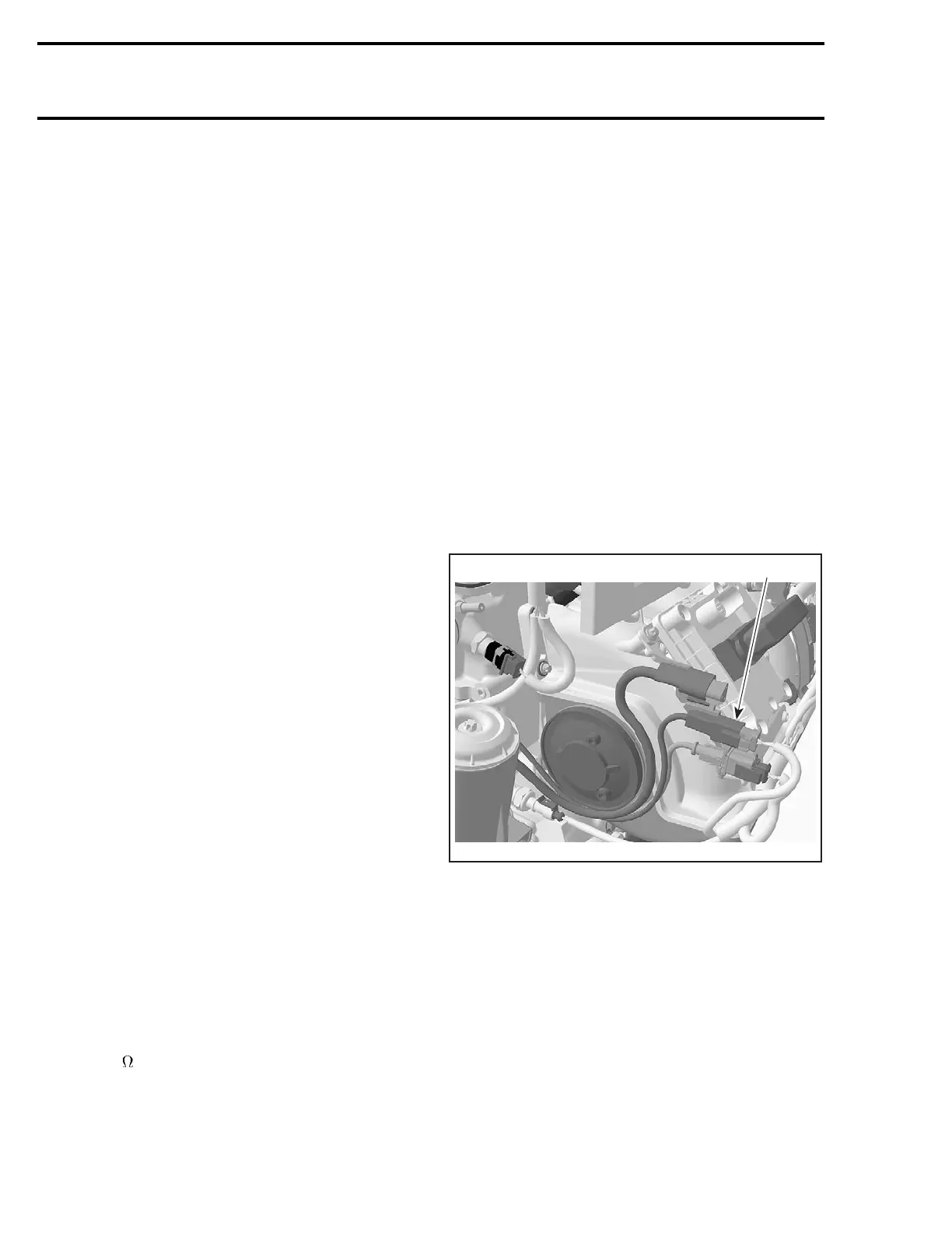
CRANKSHAFT POSITION
SENSOR (CPS)
1
R1503motr169A
TYPICAL
1. CPS connector
Ensure that information center works. Needles
will sweep, LED and LCD segments will turn on
when the safety lanyard is installed. Check for
RPM display at the information center while crank-
inginenginedrownedmode. PressandHOLD
throttle lever then press start/stop button. 800 -
1000 RPM should display. Otherwise perform the
following tests.
122 smr2005-013

 Loading...


