Section 08 STEERING SYSTEM
Subsection 02 (OFF-POWER ASSISTED STEERING SYSTEM (O.P.A.S.))
1
F18K0VA
2
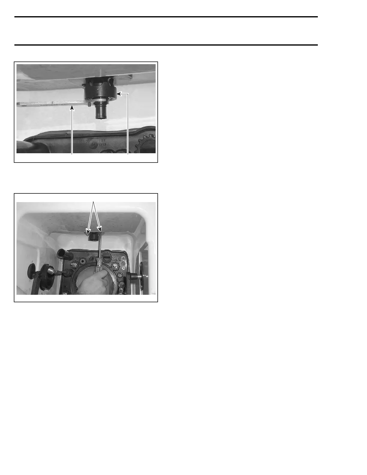
1. O.P.A.S. cylinder nut wrench
2. Valve
Remove 2 Phillips screws no. 33 from valve collar.
1
F18K0WA
TYPICAL
1. Phillips screws
Remove valve downwards from pump tunnel.
Disassembly and Assembly
Unscrew the bottom nut of valve completely, this
will release all parts from the valve body.
Check if the O-ring no. 34 is brittle or hard. replace
if need be.
Assemble all parts and torque the bottom nut to
7N•m(62lbf•in).
Installation
Installation is the reverse process of removal,
make sure of the following when doing installa-
tion:
– Check for cracks on formed hose no. 29,
change if necessary.
– Install formed hose on valve. Torque clamp
no. 35 manually to 4 N•m(35lbf•in)
– Install a new gasket no. 36.
– Install the valve.
– Torque Phillips screws no. 33 to 2.2 N•m
(19 lbf•in).
– Install water hoses no. 10 on valve.
– Tighten gear clamps no. 30 manually to 1.7 N•m
(15 lbf•in).
WATER HOSE
GTX Series, Wake and RXT Models
Removal
Removal procedure for RH and LH water hose
no. 10 is same.
Remove side vane no. 1 and cylinder support no. 6
as mentioned above.
Remove gear clamps no. 30 to remove water
hose no. 10 from valve no. 31.
Pull out the water hose from exterior.
Installation
Installation is the reverse process of removal,
make sure of the following when doing installa-
tion:
– Water hose must be installed from the outside
to the inside of hull by turning it, oriented to-
wards valve.
– Tighten gear clamps no. 30 manually to 1.7 N•m
(15 lbf•in).
CROSS SUPPORT PLATE
Removal
For LH Side Cross Support Plate
Remove inlet hose, exhaust pipe and muffler (re-
fer to EXHAUST SYSTEM).
For RH Side Cross Support Plate
Remove resonator (refer to EXHAUST SYSTEM).
248 smr2005-039

 Loading...


