Section04ENGINEMANAGEMENT(15034-TEC)
Subsection 03 (COMPONENT INSPECTION, REPLACEMENT AND ADJUSTMENT)
The leakage test is validated when performing the
FUEL DELIVERY SYSTEM DIAGNOSTIC FLOW
CHART elsewhere in this section.
Electrical Test
Voltage Test
Safety lanyard must be on DESS post.
Using the vehicle communication kit (VCK) with
the B.U.D.S. software, energize the fuel injector
from the Activation tab.
If the injector does not work, disconnect the con-
nector from the injector.
Install a temporary connector on the injector with
wireslongenoughtomaketheconnectionout-
side the bilge and apply voltage (12 V) to this test
harness.
CAUTION: While doing fuel injector electrical
test, do not apply continuous voltage to the
connector. This can damage the injector.
This will validate the injector mechanical and elec-
trical operation.
If it does not work, replace it. If it works, continue
procedure.
Using B.U.D.S., activate injector while probing ter-
minal 2 (of injector on harness side) and battery
ground.
– If 12 V is read, check continuity of circuit as per
following table. If it is good, try a new ECM.
CIRCUIT NUMBER
(ECM CONNECTOR “A”)
INJECTOR
NUMBER
A-15
1
A-33 2
A-14 3
– If it does not read 12 V, check continuity of cir-
cuit as per following table. If it is good, try a
new MPEM.
CIRCUIT NUMBER
(AMP CONNECTOR NO. 2)
INJECTOR
NUMBER
2-16
1
2-17 2
2-18 3
Resistance Test
Reconnect the injector and disconnect the ECM
connector A.
Remove safety lanyard and wait 15 seconds. Dis-
connect engine connector.
CAUTION: Before unplugging engine connec-
tor, always remove safety lanyard and wait 15
seconds. Otherwise, damage to CAPS may oc-
cur.
Using a multimeter, check resistance value be-
tween terminals as follows.
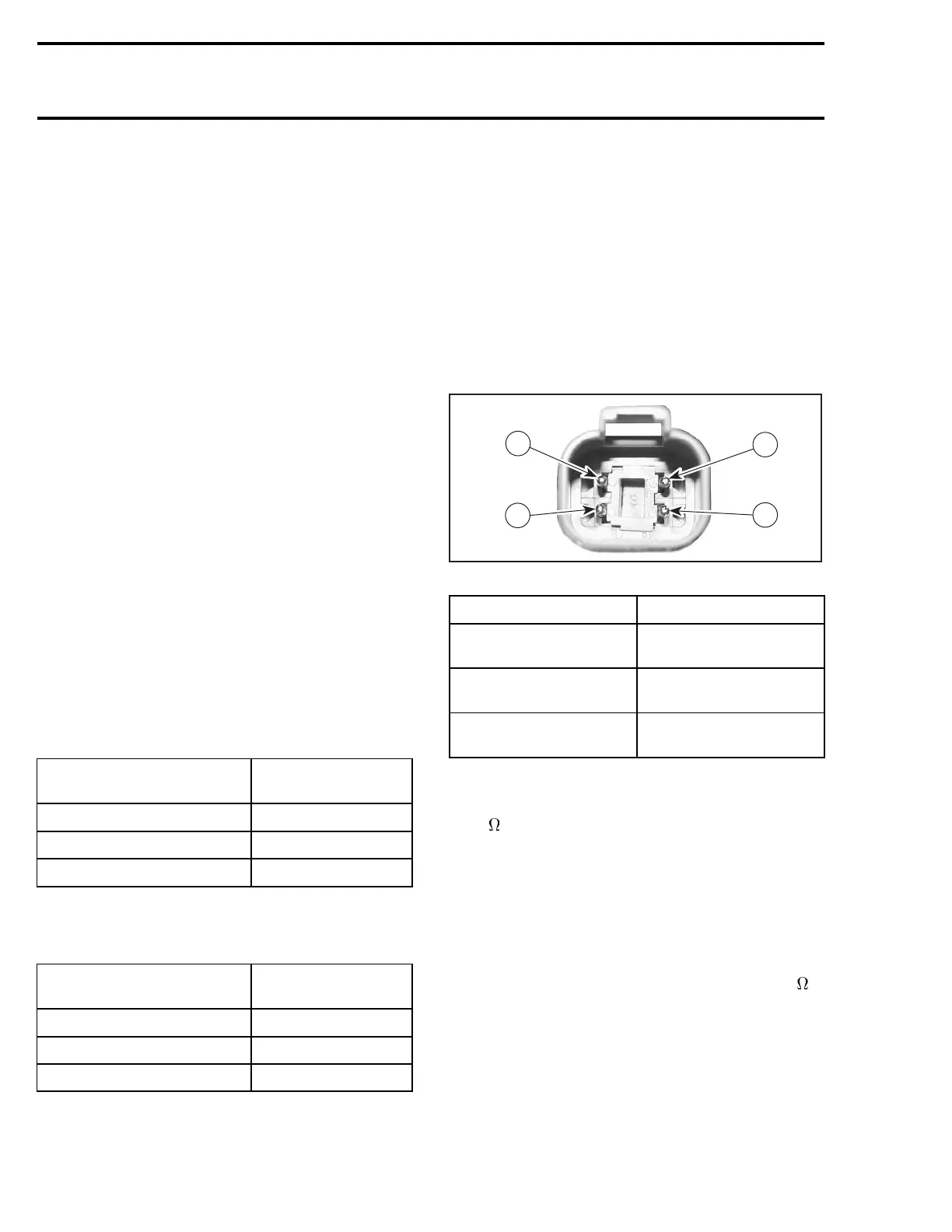
4
R1503motr192A
1
2
3
ENGINE CONNECTOR
COMPONENT TERMINAL LOCATION
Fuel injector cylinder 1
1 (engine connector) and
A-15 (ECM connector)
Fuel injector cylinder 2
2 (engine connector) and
A-33 (ECM connector)
Fuel injector cylinder 3
3 (engine connector) and
A-14 (ECM connector)
4-TEC Naturally Aspirated Models
The resistance should be between 11.4 and
12.6
.
If resistance value is correct, try a new ECM. Refer
to ECM AND MPEM in this section.
If resistance value is incorrect, repair the wiring
harness/connectors or replace the wiring harness
between ECM connector and fuel injector.
All 4-TEC Supercharged Models
The resistance should be between 14 and 15
.
If resistance value is correct, try a new ECM. Refer
to ECM AND MPEM in this section.
If resistance value is incorrect, repair the wiring
harness/connectors or replace the wiring harness
between ECM connector and fuel injector.
116 smr2005-013
 Loading...


