Section06ELECTRICALSYSTEM
Subsection 01 (IGNITION SYSTEM)
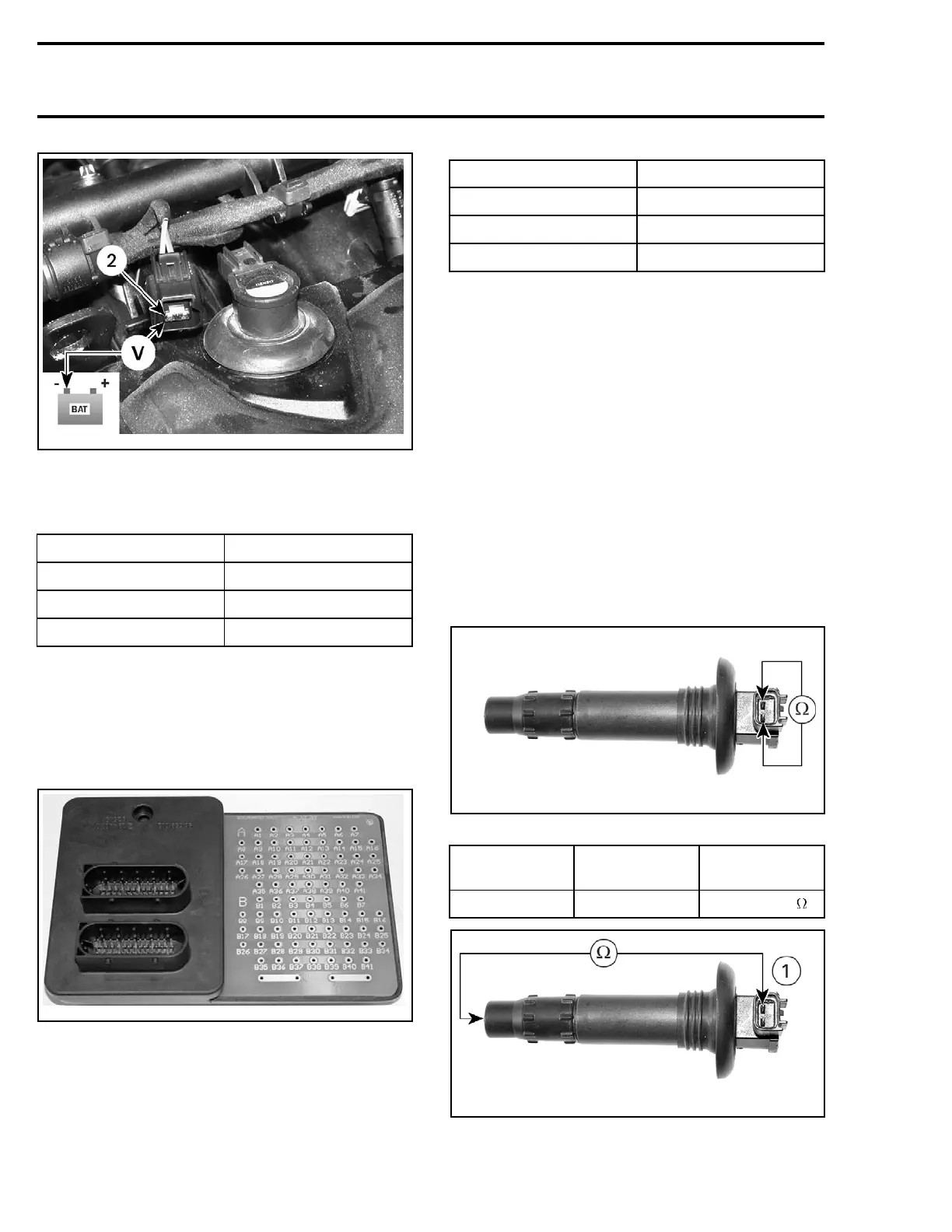
smr05-015-001_a
The voltage should be 12 V.
If 12 V is NOT read, check continuity of appropriate
circuit.
COMPONENT CIRCUIT NUMBER
Cylinder 1
2-16
Cylinder 2
2-17
Cylinder 3
2-18
If 12 V is read, disconnect the ECM connector A
and check the continuity of appropriate circuit.
NOTE: For this test, use the ECM adapter
(P/N 420 277 010) to probe ECM connector.
Refer to ENGINE MANAGEMENT for more infor-
mation.
420277010
COMPONENT CIRCUIT NUMBER
Cylinder 1
41
Cylinder 2
1
Cylinder 3
29
If wiring harness is defective, repair the connector
or replace the wiring harness between ECM con-
nector and the ignition coil.
If wiring harness is good, try a new ECM.
IGNITION COIL
Resistance Test
An ignition coil with good resistance measure-
ment can still be faulty. Voltage leak can occur
at high voltage level which is not detectable with
an ohmmeter. Replacing the ignition coil may be
necessary as a test.
Remove ignition coil from spark plug.
Using a multimeter, check the resistance in both
primary and secondary windings.
smr05-015-002_a
PRIMARY CIRCUIT
CIRCUIT TERMINAL
RESISTANCE
@20°C(68°F)
Primary 1and2 0.85 - 1.15
smr05-015-002_b
SECONDARY CIRCUIT
148
smr2005-015
 Loading...


