Section 06 ELECTRICAL SYSTEM
Subsection 04 (INSTRUMENTS AND ACCESSORIES)
– Push sensor in seal.
– Plug connector.
NOTE: This sensor turns the LED to ON if the
connector has been forgotten unconnected even
when there is enough oil in tank.
VTS Switch
RXP Models
Always confirm first that the fuse is in good con-
dition.
Disconnect BLACK wire, BLUE/WHITE wire and
GREEN/WHITE wire of VTS switch.
Using the multimeter FLUKE 111 (P/N 529 035
868), connect test probes to switch BLACK and
BLUE/WHITE wires; then, connect test probes to
switch BLACK and GREEN/WHITE wires.
Measure resistance; in both test it should be high
when button is released and must be close to zero
when activated.
VTS Motor
RXP Models
Always confirm first that the fuse is in good con-
dition.
The fuse is located on the MPEM module.
Motor condition can be checked with the multi-
meter FLUKE 111 (P/N 529 035 868). Install test
probes on both RED/PURPLE/WHITE and ground
wires of the 2-circuit connector housing. Measure
resistance, it should be close to 1.5 ohm.
If motor seems to jam and it has not reached the
end of its stroke, the following test could be per-
formed.
First remove motor, refer to VARIABLE TRIM SYS-
TEM. Then manually rotate worm to verify VTS
system actuating mechanism for free operation.
Connect motor through a 15 A fuse directly to the
battery.
Connect wires one way then reverse polarities to
verify motor rotation in both ways.
If VTS actuating mechanism is correct and the mo-
tor turns freely in both ways, VTS module could be
defective.
If VTS motor does not stop at the end of its stroke
while installed, the motor could be defective.
VTS Control Module
RXP Models
It receives its current from the battery. It is pro-
tected by its own fuse located on the MPEM mod-
ule.
Resistance Test
Disconnect BROWN/BLACK wire and BROWN/
WHITE wire of VTS control module.
Connect test probes of a multimeter to
BROWN/BLACK wire and BROWN/WHITE wire
of VTS control module.
Push on VTS switch down position until motor
stops.
Read the resistance on the ohmmeter, it should
indicate a resistance of 24 ohms ± 1%.
Push on VTS switch up position until motor stops.
Read the resistance on the ohmmeter, it should
indicate a resistance of 167 ohms ± 1%.
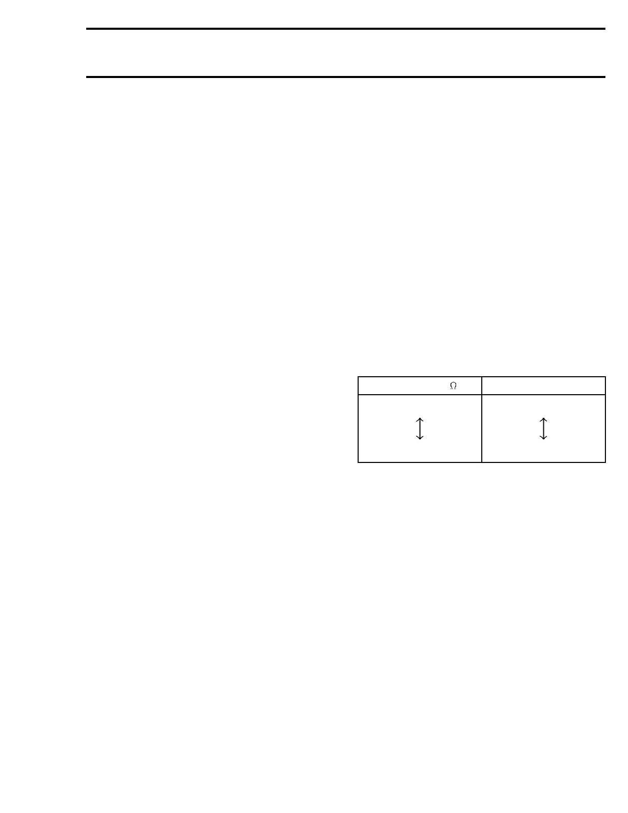
RESISTANCE ( ) NOZZLE POSITION
167 ± 1%
24 ± 1%
UP
DOWN
NOTE: If the VTS control module passes this re-
sistance test, it does not mean it is in perfect con-
dition.
Water Temperature Sensor
The water temperature sensor is integrated with
the speed. As a result, that sensor has 3 wires
instead of 2.
B.U.D.S.canbeusedtocheckitsoperation. Look
in the Monitoring tab.
To check if the water temperature sensor is oper-
ational, select the water temperature mode in the
Information Center.
With a garden hose, spray the speed sensor with
water. The temperature reading on the Informa-
tion Center should adjust to the water tempera-
ture.
If not, replace the speed sensor.
smr2005-018 179

 Loading...


