Section07PROPULSION
Subsection 02 (DRIVE SYSTEM)
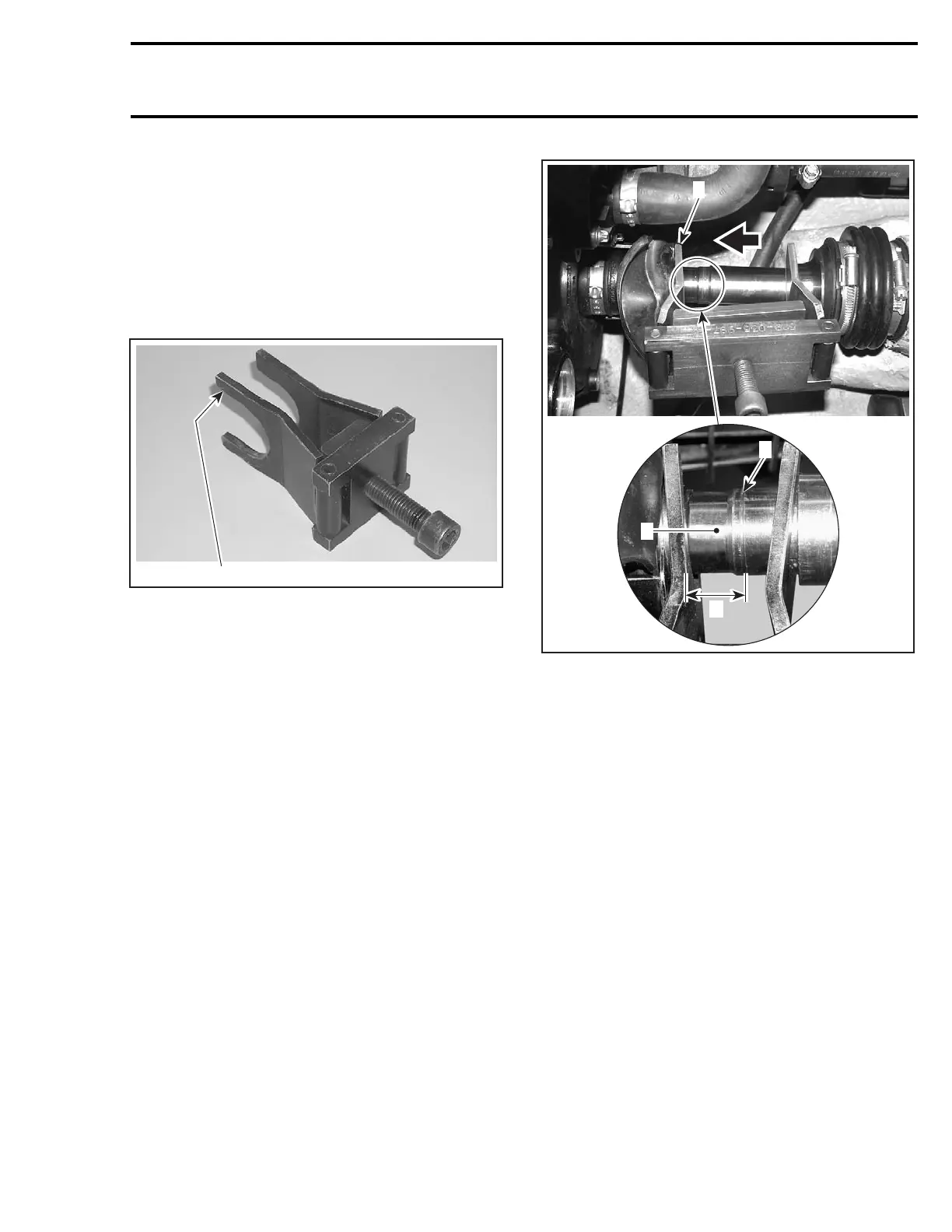
Turn screw clockwise so that the tool pushes the
floating ring no. 1 rearwards to expose the circlip
no. 2. Do not remove circlip at this time.
NOTE: This step is done to ensure floating ring is
free and not stuck on the drive shaft no. 3.
Remove drive shaft/floating ring tool and drive
shaft holder.
Reinstall drive shaft/floating ring tool as shown.
1
F18I0OA
TYPICAL
1. Largest opening on PTO seal side
F18I0TA
1
2
3
A
TYPICAL
1. Largest opening here
2. Telltale groove
3. Lubricate O-rings contact area
A. 18 mm (.71 in)
Turn screw clockwise so that the tool pushes the
PTO seal forward and the drive shaft to the rear to
expose the O-rings contact area. Continue to pull
drive shaft out until there is a distance of 18 mm
(.71 in) between the telltale groove and the tool
edge. Lubricate O-rings contact area with BOM-
BARDIER LUBE (P/N 293 600 016).
NOTE: This is necessary to ease drive shaft re-
moval later in this procedure.
Removedriveshaft/floatingringtool.
Reinstall drive shaft holder tool.
smr2005-020 207

 Loading...


