Section 01 MAINTENANCE
Subsection 04 (SPECIAL PROCEDURES)
WARNING
Make sure to safely secure the watercraft.
– With the engine still running at 3500 RPM, in-
stall a hose pincher to the coolant line going to
the oil cooler.
WARNING
Certain components in the engine compart-
ment may be very hot. Direct contact may re-
sult in skin burn. Do not touch any electrical
parts or jet pump area when engine is run-
ning.
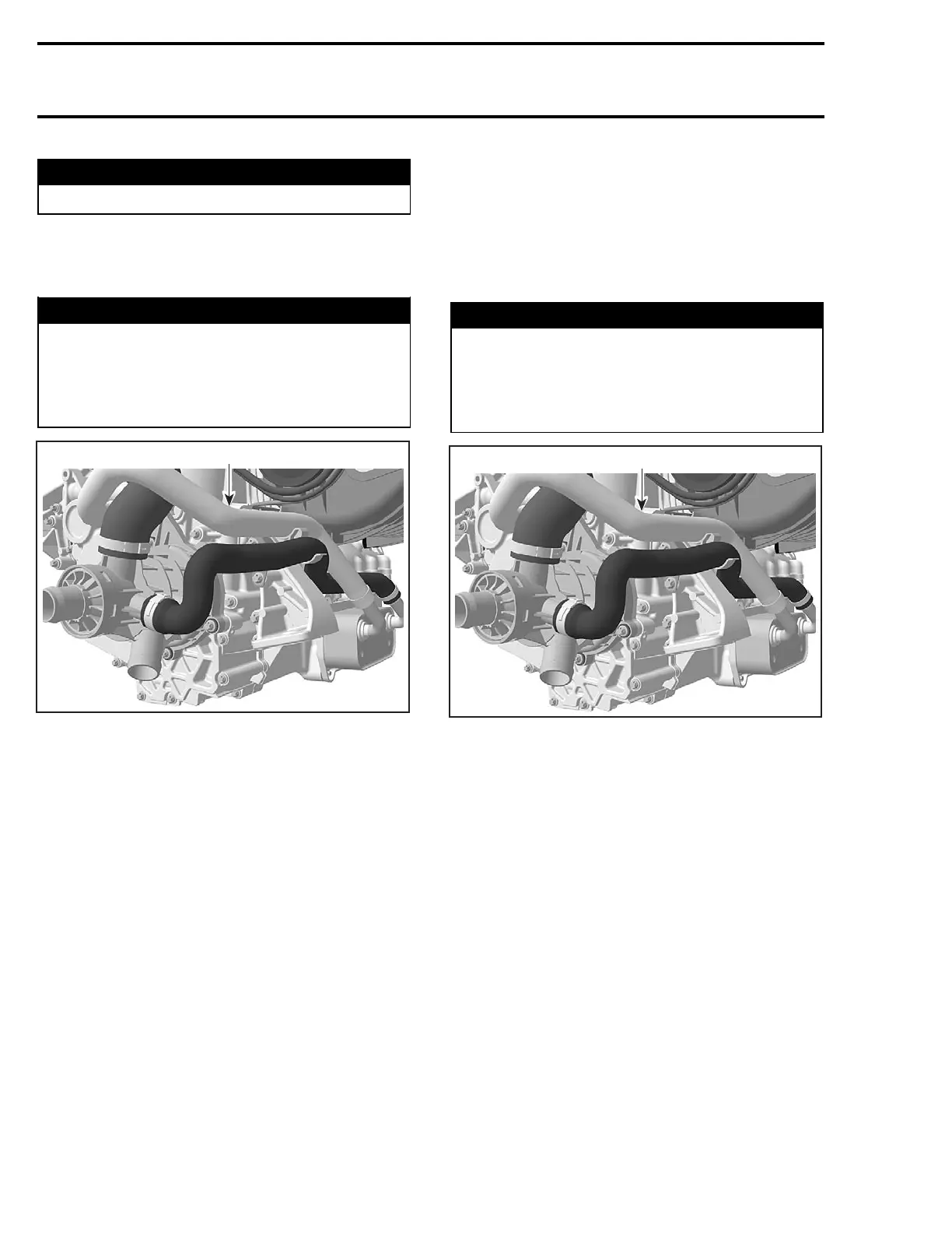
1
F18E1QA
1. Oil cooler coolant inlet hose
– Continue to run the engine at 3500 RPM for 15
more minutes (20 minutes total run time).
– Shuttheengineoff.
– Remove the hose pincher on the coolant line
goingtotheoilcooler.
CAUTION: Hose pincher must be removed pri-
or to operating the watercraft. Failure to do
this will result in damage to the engine.
– Change the oil and filter again.
– Procedure is now completed.
Procedure Connected to a Flush Kit
– On drive shaft, remove the C-clip then move
forward the ring seal carrier. Refer to DRIVE
SYSTEM section.
CAUTION: Make sure that the ring seal carrier
is not in contact with th
e PTO seal assembly,
neither with the carbon ring.
– Connect a flush kit to the coolant line.
CAUTION: Never run engine without supplying
water to the exhaust cooling system when wa-
tercraft is out of water.
– Run the engine for 5 minutes at 3000 RPM.
– With the engine still running at 3000 RPM, in-
stall a hose pincher to the coolant line going to
the oil cooler.
WARNING
Certain components in the engine compart-
ment may be very hot. Direct contact may re-
sult in skin burn. Do not touch any electrical
parts or jet pump area when engine is run-
ning.
1
F18E1QA
1. Oil cooler coolant inlet hose
– Continue to run the engine at 3000 RPM for 15
more minutes (20 minutes total run time).
– Shut off the engine.
– Remove the hose pincher on the coolant line
going to the oil cooler.
CAUTION: Hose pincher must be removed pri-
or to operating the watercraft. Failure to do
this will result in damage to the engine.
– Change the oil and filter again.
– Move rearward the ring seal carrier and reinstall
the C-clip. Refer to DRIVE SYSTEM section.
14 smr2005-005
 Loading...


