Section 07 BODY AND HULL
Subsection 01 (SUSPENSION (iS))
Reinstall reservoir plug and tighten it to 1 N•m
(9 lbf•in).
Hydraulic Pump Operation Test
Connect a jumper from the positive (30 A fused
jumper) and negative side of the battery to the hy-
draulic pump connector (2-pins connector).
The hydraulic pump should activate and suspen-
sion should go up or down.
Reverse the jumpers and the suspension should
reverse direction.
If the hydraulic pump does not run, check con-
nectors and wires. Replace hydraulic pump as re-
quired.
If hydraulic pump turns, perform the
HYDRAULIC
PUMP CURRENT DRAW
test to confirm pump op-
eration.
Hydraulic Pump Current Draw
If the current draw is to high, the iS module acti-
vates an internal protection.
This operation can be done using B.U.D.S. soft-
ware. Refer to
COMMUNICATION TOOLS AND
B.U.D.S. SOFTWARE
subsection to connect
B.U.D.S.
Activate the suspension by pressing iS up and iS
Down s and check voltage.
smr2009-041-053_a
ACTIVATI
ON AND IS TABS
1. B.U.D.S. ammeter
2. iS UP
3. iS down
CURRENT
iS UP
16 - 20 A
iS Down
15 - 18 A
If values is near specifications, check connections
and wires.
If wires and connectors are good, perform the iS
module output voltage test. Refer to
IS MODULE
in this subsection.
If the current draw is excessive, replace the hy-
draulic pump.
Hydraulic Pump Removal
(as a Unit with Actuator)
To work on many parts of suspension system, the
removal of the hydraulic pump and actuator as an
unit is necessary.
1. Remove
SHOCK ABSORBER
and
SPRINGS
.
See procedures in this subsection.
2. Unplug the hydraulic pump connector from the
iS module.
3. Cut any locking ties securing the pump harness
to vehicle harness.
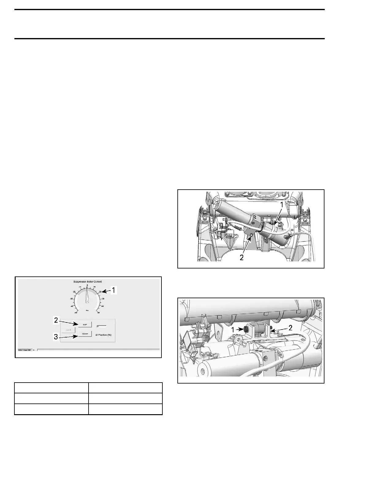
4. Remove clamp and bolt securing the hydraulic
pump from suspension base.
smr2009-041-016_b
1. Hydraulic pump clamp
2. Retaini
ng bolt
5. Remove actuator link bolt.
smr2009-041-029_a
1. Actuator link bolt
2. Link support on the top of suspension base
6. Remove screws retaining the actuator holder.
454 smr2009-041

 Loading...

