Drive Setup CDHD
100 User Manual
5 .6 .8 D a isy Chain – C8
N ote: EB m odels do not have Daisy Chain port .
The CDHD can be addressed and controlled on a daisy-chained RS232 line.
I n a daisy-chain RS232 configuration, all drives must be daisy-chained through
t he C8 connector. Each drive must have a unique address to enable its
identification on the net work.
A daisy-chained drive can be assigned an address from 1 t o 99 by setting the
rotary switches on the drive. When configuring a daisy-chain, address 0 cannot
be used.
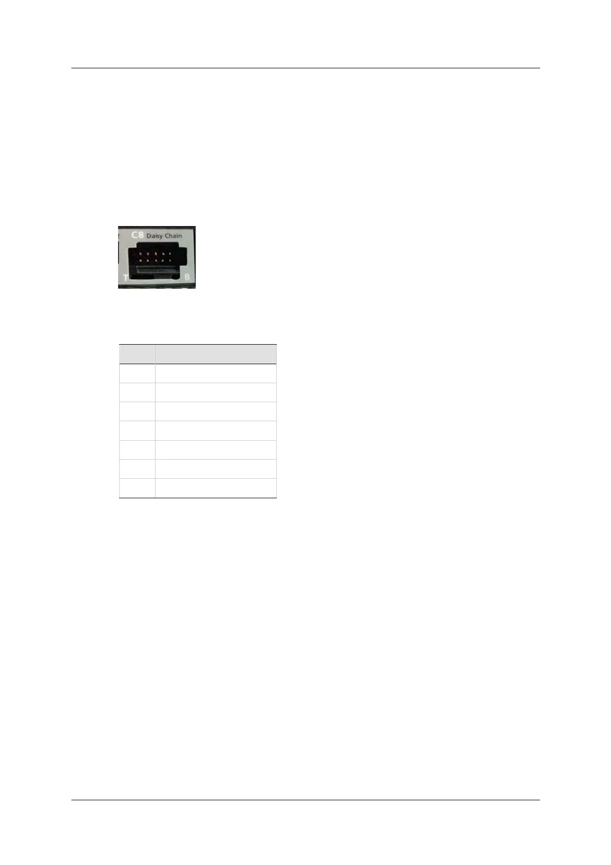
Figur e 5 - 1 3 . Da isy Chain Port
Ta ble 5 - 3 3 . Daisy Cha in I nt er face
Pin Fun ct ion
1 DC Shield
2 Unused
3 RXD
4 GND
5 TXD
6 GND
7-10 Unused
5 .6 .9 D r ive Addr ess – Rot ary Sw it ch
N ote: EB models do not have rotary switches.
The CDHD has t wo 10-position rotary switches, accessible from the front of the
unit . The switches are used to set the drive address. When there is m ore t han
one drive on a daisy-chain or CANbus network, each drive must have a unique
address to enable its identification on the network.
Use the two rotary switches t o set the drive address for both CAN and serial
com munication.
For Et hernet-based motion buses, the switch has no functional use for either the
drive or the network. It can be used at the application level to identify specific
drives on a network.
Each switch has 10 positions:
The upper switch positions are set as tens: 10, 20, 30 … 90
The lower switch positions are set as ones: 0, 1, 2 … 9
N ot es: I f two or m ore drives are connected to the network, address 0 cannot
be used. Only a singular drive may have the address 0.
Two drives in the same network cannot have the sam e address.