CDHD Drive Setup
User Manual 111
Ta ble 5 - 4 6 . Logic Pow er 2 4 V I nput I nt erface Ma t ing Conne ctor
I te m All M odels
Manufacturer Molex
Housing and
2-pin crimp
436450200 (supplied) and
0430300001 (supplied)
Spring term inal Not available
Wired STO Servot ronix CONr00000004-AS (supplied)
Wire gauge 26–28 AWG
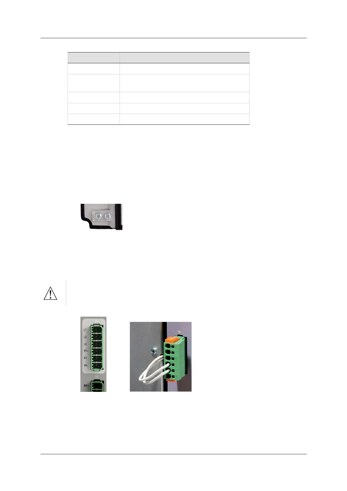
5 .8 .3 AC I npu t an d Regen er at ion Resist or
On t he CDHD 400/480 VAC m odels, AC I nput and Regen Resist or are
combined on one connect or, and use the following int erfaces:
P3 on CDHD-003/ CDHD-006/ CDHD-012
P5 on CDHD-024/ CDHD-030
1 . Connect the AC input voltage ground wire to the PE terminal, located on the
CDHD front panel. Use an M4 ring or spade term inal.
Figure 5 - 2 3 . Functional Ground – PE Ter m ina l
2 . Connect L1, L2 and L3 (for bus power).
3 . I f the application requires a regenerat ion (regen) resistor, connect the regen
resistor between terminals B1+ and B2.
Pre ven t inrush surge :
After switching on bus power, wait 1 minut e before switching On again,
regardless of time in Off state.
Figure 5 - 2 4 . AC I nput and Regenerat ion Re sistor I nterfaces