CDHD Drive Setup
User Manual 85
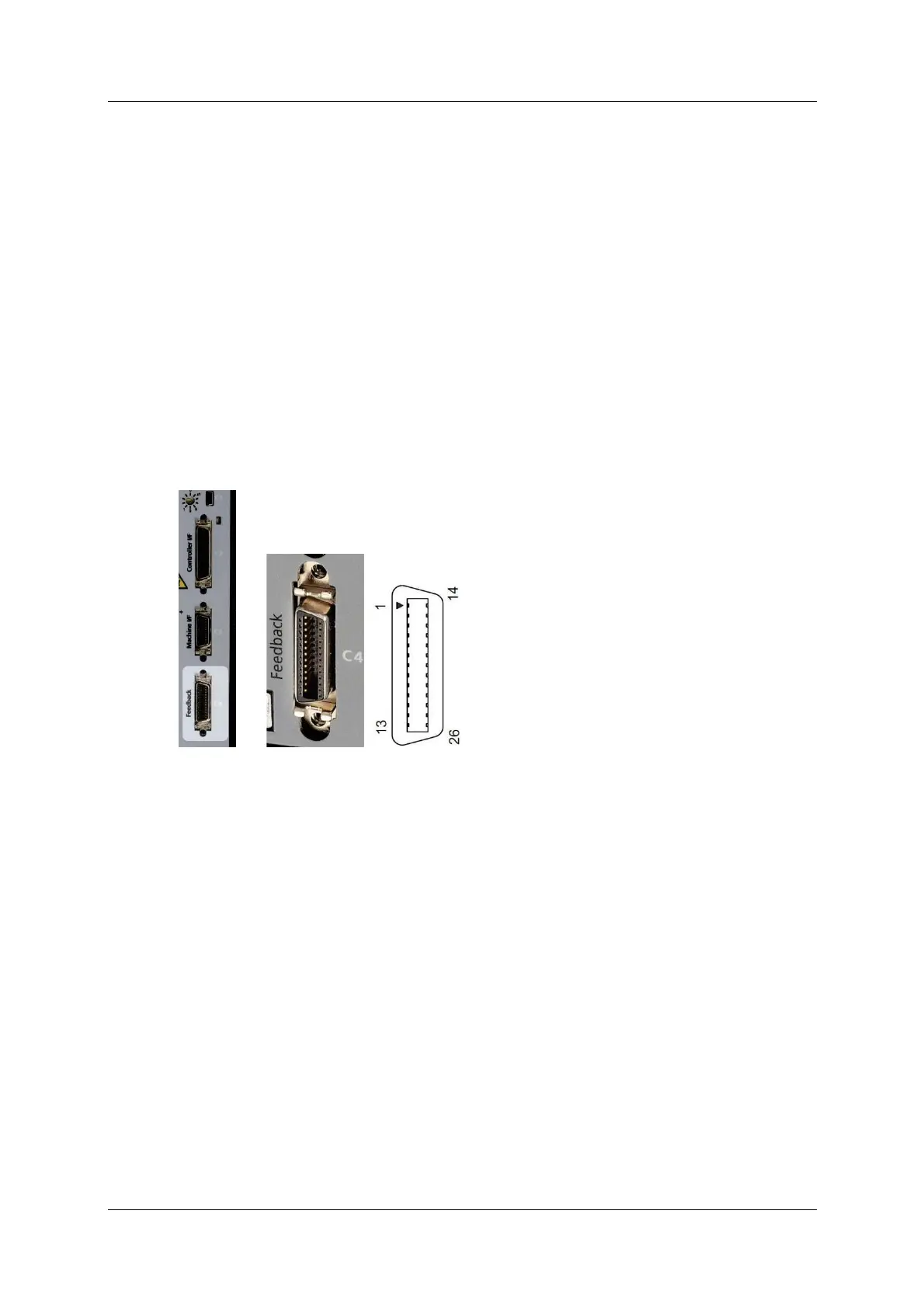
5 .6 .3 M ot or Fe edback – C4
Motor Fe e dback uses interface C4 .
Wire the m otor feedback interface according to the type of feedback device to be
used in your application. Refer to the guidelines following the pinout table below.
Pins 1, 2, 14 and 15 have dual functionality.
Pin 25 for the m ot or tem perat ure sensor is connect ed internally in the drive t o
CDHD ground.
Unused pins must rem ain unwired.
N ot es regarding serial comm unication encoders, such as Tam agawa and Nikon:
Serial encoder data is bidirectional.
Serial encoder clock is only output.
Low-voltage indication comes directly from the encoder; the drive does
not have the capability t o verify encoder batt ery volt age.
Figur e 5 - 8 . Motor Fe e dback I nt e rface
PB Models – Mot or Fe e dba ck
CDHD PB models do not have a Machine I / F interface.