CDHD Wiring
User Manual 57
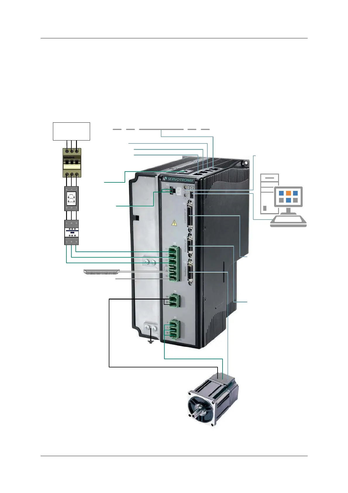
4 .6 CDH D- 0 1 2 ( 4 0 0 / 4 8 0 V AC)
W iring and Pin Assignm ents
Figur e 4 - 2 1 . Servo Syst e m W iring, 3 - Phase – CDHD - 0 1 2
( 4 0 0 / 4 8 0 VAC)
Functional
Ground
Motor Feedback
Motor Power
To PC
USB mini-B cable
* Regenerative
Resistor (optional)
Motor Brake
24 VDC 1.3A max
Circuit
Breaker
or Fuses
Magnetic
Contactor
Line Filter
(optional)
Rotary Switches
Drive addressing
Mains
Three-Phase
Max. 528 VAC L-L
Daisy Chain
OUT
RS232
EtherCAT
or CAN
IN
To Host Controller
Voltage reference input
Pulse and direction input
Encoder equivalent output
6x digital inputs
3x digital outputs
1x analog output
To Additional IOs
5x digital inputs
3x digital outputs
1x fault relay
Secondary feedback
Logic PS
24 VDC 3.5A*
Bus –
* Internal 22Ω 300W. For higher power, external regen resistor
is required; refer to the user manual
Refer to EMI Suppression in the user manual
STO
Safe Torque Off
Connect to 24 VDC PS
or use bypass plug