Drive Setup CDHD
72 User Manual
5 .3 EM I Suppression
5 .3 .1 CE Filterin g Te ch niqu es
The CDHD drive complies with the CE standards specified in the section
St andards Com pliance. Proper bonding, grounding and filtering techniques must
be applied in order t o m eet this standard.
Noise currents often occur in two types. The first is conducted emissions that are
passed through ground loops. The quality of the system grounding schem e
inversely determines the noise amplitudes in the lines. These conducted
em issions are of a comm on-m ode nature from line to neutral (or ground). The
second is radiat ed high-frequency emissions usually capacitively coupled from
line-to-line and are differential in nature.
To properly m ount the EMI filters, the enclosure should have an unpainted
m et allic surface. This allows for m ore surface area to be in contact wit h the filt er
housing and provides a lower impedance path between this housing and the back
plane. The back panel, in turn, has a high frequency ground strap connection to
the enclosure fram e or earth ground.
5 .3 .2 Grounding
When connecting the CDHD to other control equipm ent , be sure to
follow two basic guidelines to prevent dam age to t he driv e:
The CDHD m ust be grounded via the earth ground of the main AC
volt age supply.
Any motion controller, PLC or PC that is connected to the CDHD
m ust be grounded to the same earth ground as the CDHD.
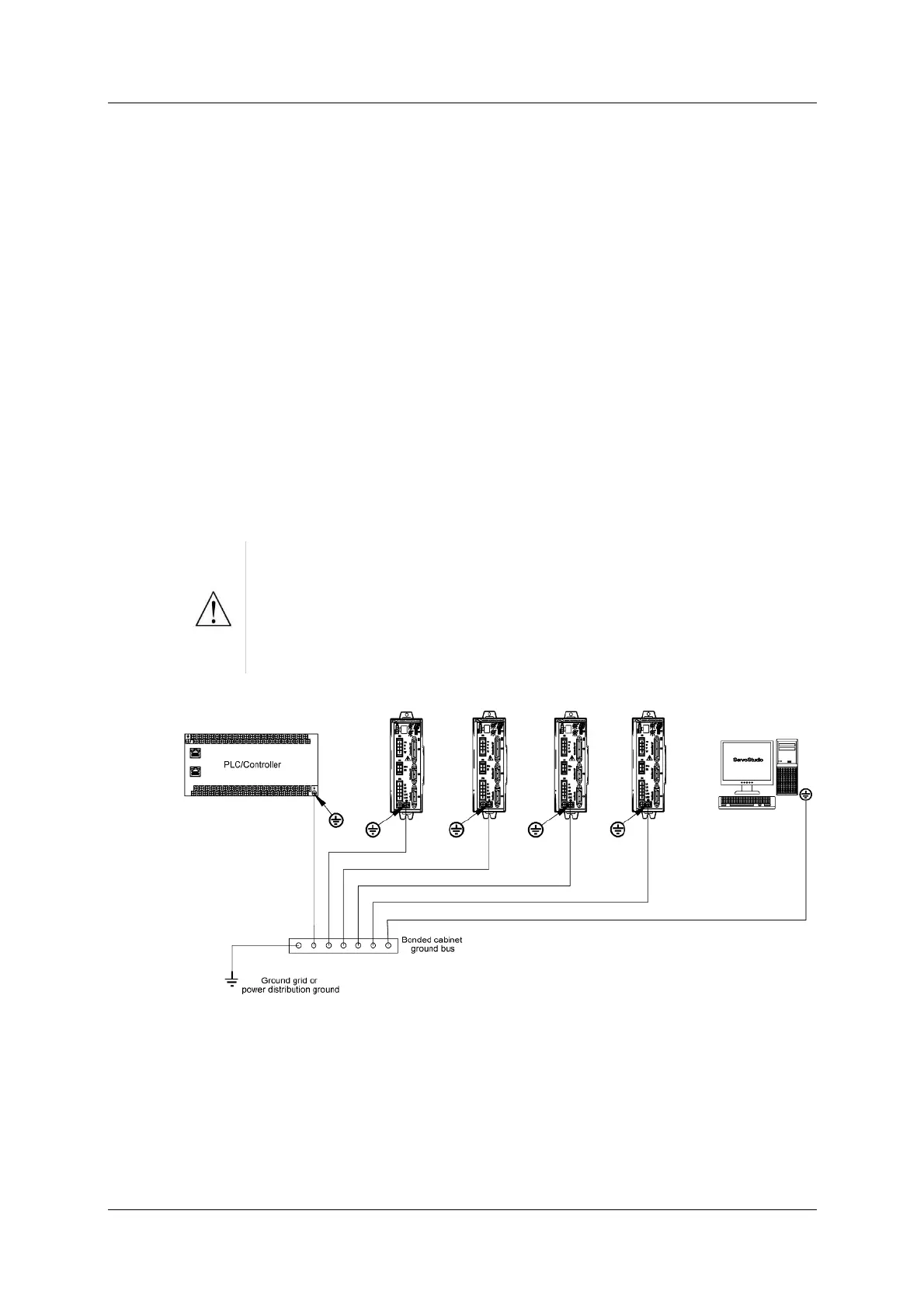
Figur e 5 - 2 . CD H D System Grounding
Syst em grounding is essential for proper perform ance of the drive system .
The AC input voltage ground wire must be connected to the PE terminal, located
on the CDHD front panel. This is necessary for bot h safet y and EMI reduction.
Use a single point ground for the system (start wiring) to avoid ground loops.
It is strongly recommended that the CDHD be mounted to a metallic back panel,
and that a high frequency ground be provided t o connect the back panel t o earth