CDHD Drive Setup
User Manual 83
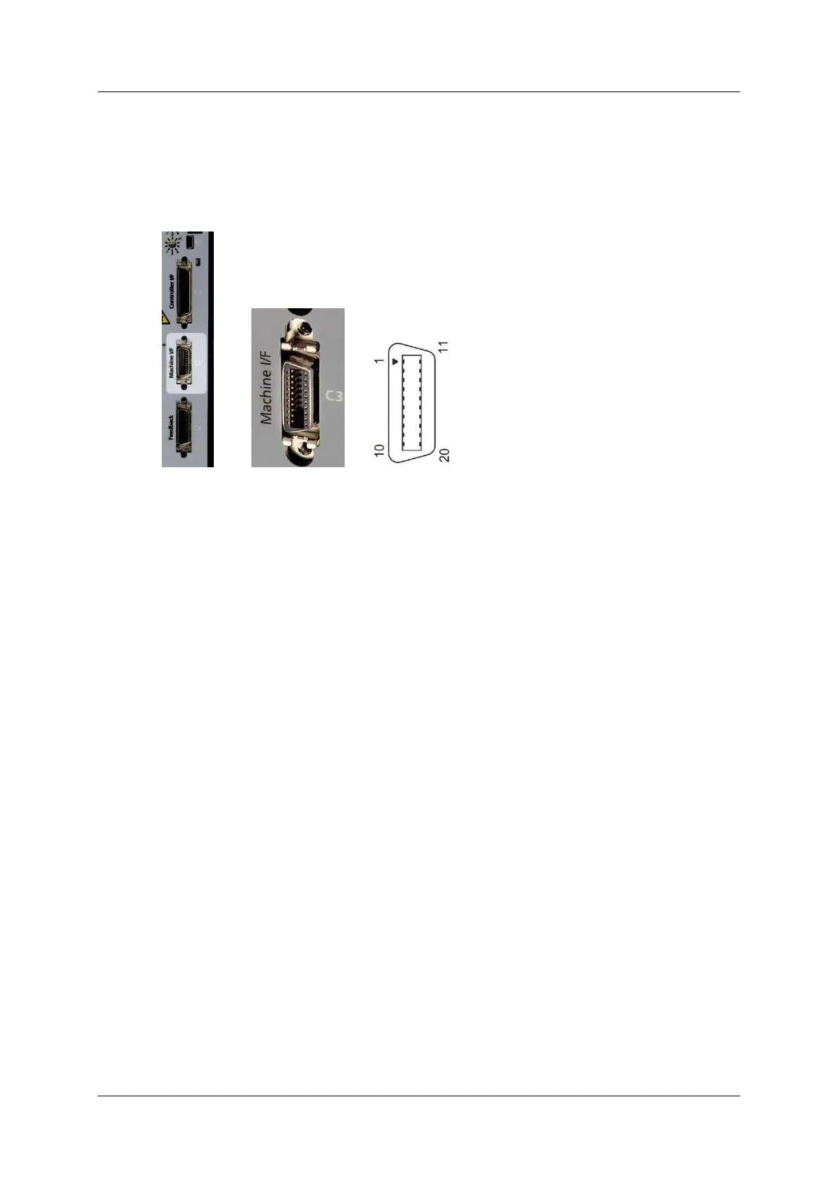
5 .6 .2 M achin e I nt er face – C3
Machine I / Os are connected through interface C3 .
Wire the m achine inputs and outputs according to the requirements of your
application.
Unused pins must rem ain unwired.
Figur e 5 - 7 . Machine I / O I nterface
Refer to the m achine interface wiring diagram in Figure 4-31.
PB Models – Ma chine I / Os
CDHD PB models do not have a Machine I / F interface.
AP/ AF M odels – M achine I / Os
To preserve isolation of the digital I / Os, connect a 24 VDC source t o pin 9.
Connect the return of the 24 VDC supply to pin 19, which functions as the
ground path for the outputs.
N ote: The 24 VDC supply and return can be connected on either the Controller
interface (C2) or the Machine interface (C3), but it is not necessary to
connect it to both.
EC M odels – Ma chine I / Os
Com mon output on the Controller interface (C2) and the Machine interface (C3)
are connected internally.
Com m on input on the Controller int erface (C2) and the Machine interface (C3)
are connected internally.
User can connect outputs as source or sink.
User can connect inputs as source or sink.
Refer to the Machine I nterface Wiring schem atic diagram for EC Mode ls in the
section Machine I nt erface Wiring, and the CDHD Syst em Wiring – Pin
Assignm ents diagram for EC M odels in section
Wiring and Pin Assignments.
EB Models – M achine I / Os
CDHD EB m odels do not have a Machine I / F interface.