Drive Setup CDHD
110 User Manual
Ta ble 5 - 4 3 . STO I nt erface
Pin Pin La bel Fu nct ion
1 24V STO Enable
2 GND 24 VDC Return
3
4
Ta ble 5 - 4 4 . STO I nterface Ma t in g Connector
I te m All M odels
Manufacturer Molex*
Housing and
4-pin crimp
436450400* and
0430300001*
Spring term inal Not available
Wired STO Servot ronix CONr00000004-AS (supplied)
Wire gauge 26–28 AWG
* Or equivalent.
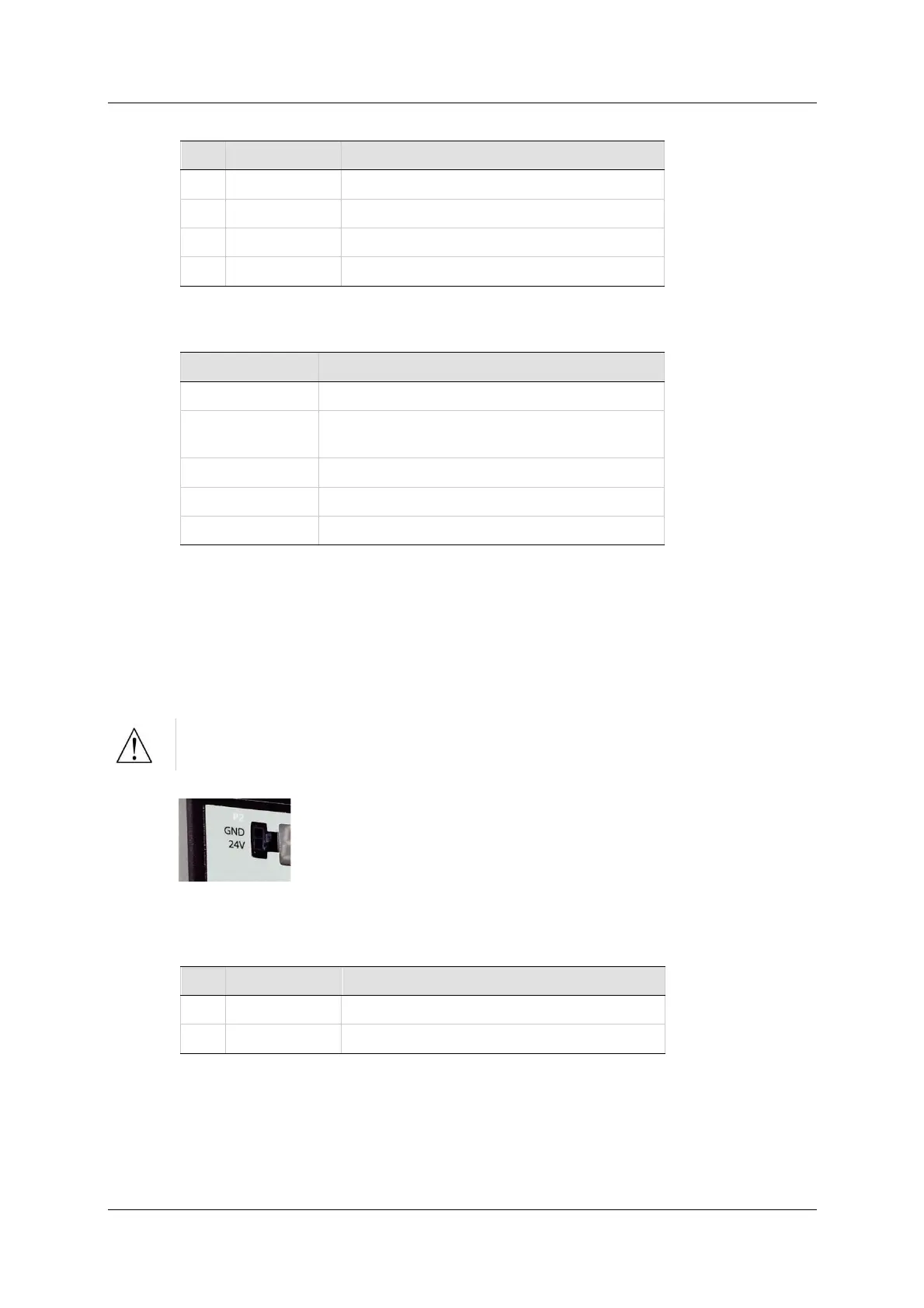
5 .8 .2 Logic Pow er 2 4 V I npu t
Logic Pow er 2 4 V uses interface P2 on all CDHD 400/ 480 VAC m odels.
This interface is used t o connect an external power supply (24V 3.15A max.)
that provides the logic voltage to the control board and to the motor brake
circuit.
Pre vent inrush surge:
After switching Logic Power Off, wait 1 minute before switching On again.
Figur e 5 - 2 2 . Logic Pow er 2 4 V I nput I nt er face
Ta ble 5 - 4 5 . Logic Pow e r 2 4 V I npu t I nt er face
Pin Pin La bel Fun ct ion
1 24V Logic In
2 GND 24 VDC Return