CDHD Application Setup
User Manual 159
Figur e 6 - 2 3 . D isable St op
Not es:
If one of the digital outputs is configured for brake control, then the brake
will be engaged as soon as the DISTI ME timer begins counting.
If the internal timeout (which is calculated according to the actual velocity
and DECSTOP) expires, the ram p down m echanism will also abort, as
indicated by 1 in the Disable St op diagram .
6 .1 4 .2 Dynam ic Brak e
Dynamic braking is a mechanism that allows a disabled drive to hold the motor.
Only the m ot or’s back-EMF is used to apply the stopping current.
The variable ISTOP is used to set the maximum current allowed during the
dynamic braking process.
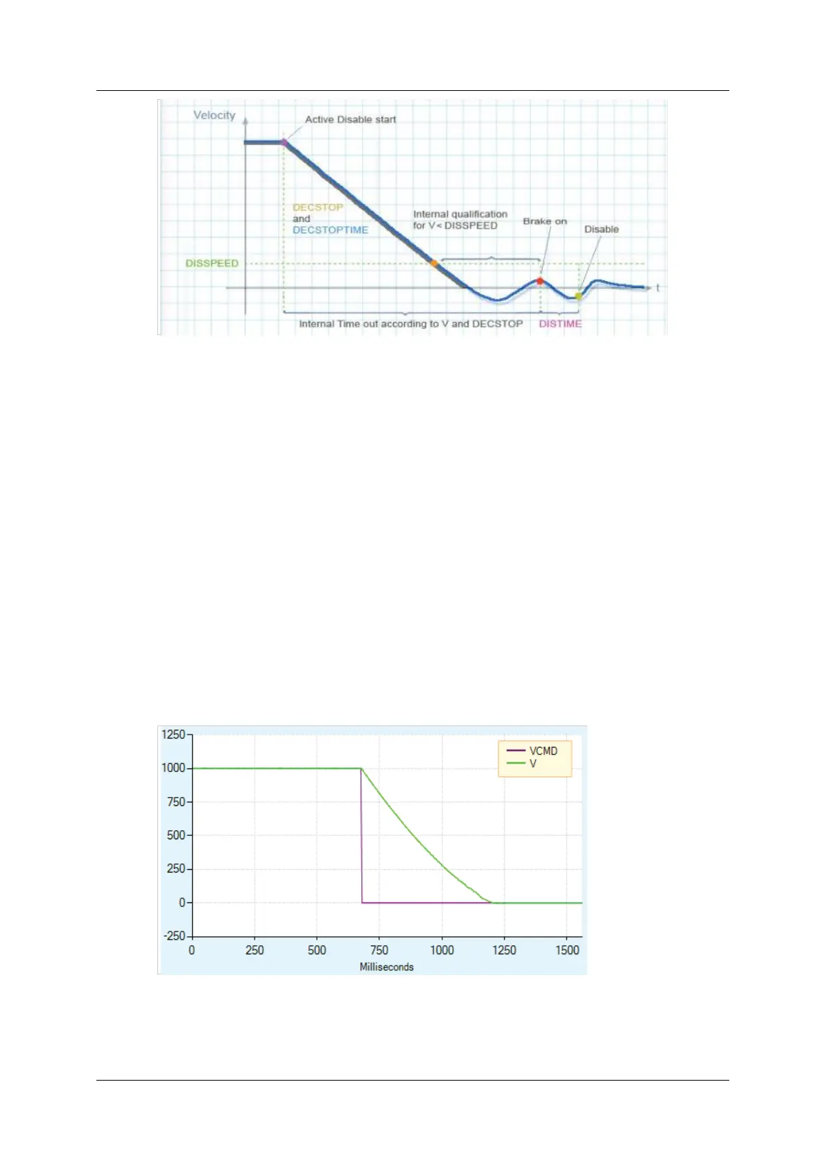
Figure 6-24 illustrates m otor coasting, that is, no Dynamic Braking (and no
Active Disable). The velocity com m and is set to 0 as soon as the drive is
disabled. The actual velocit y then decreases as a function of the syst em inertia
and friction.
Figur e 6 - 2 4 . M otor Coasting, W ithout Dyna m ic Bra k ing
 Loading...

