Drive Setup CDHD
78 User Manual
5 .6 Control Boa r d Con nect ions
The control board interfaces vary depending on the specific CDHD m odel, as
det ailed in the following t able.
The connectors for interfaces C2, C3 and C4 can be fast ened by either lat ch or
screw. The CDHD has 4/40 insert threads on these interfaces.
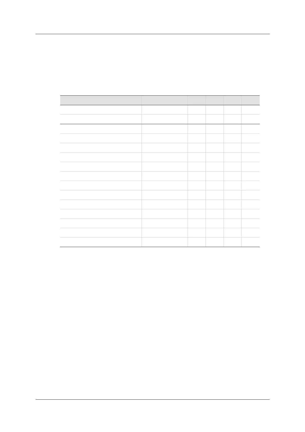
Ta ble 5 - 2 . Cont r ol Board I nte r faces
N ote: I nterfaces C3 and C4 on PB m odels are used for Mot or Brake.
Refer t o section Mot or Br ake on Power Block .
5 .6 .1 Con t roller I nter face – C2
Cont roller I / Os are connected through interface C2 .
Wire the digit al and analog inputs and outputs according t o the requirem ent s of
your application.
Unused pins must rem ain unwired.
PB Models – Cont r olle r
This interface is used for the PWM comm unication with the controller.
For C2 pin descriptions, refer to the m aster controller documentation.
Wire the controller inputs and outputs according to the requirements of your
application. Unused pins must rem ain unwired.
Fun ct ion I nt e rface AP AF EB EC
USB Serial Comm unication C1 –
RS232 Serial Communication C7
–
Cont roller C2
Pulse and direction input C2
–
Analog output C2
–
Machine C3
–
Secondary feedback input C3
–
Fault relay C3
–
Motor Feedback C4
Equivalent encoder output C4
–
Mot or feedback 8V supply C4
– –
Motor feedback resolver C4
–
Fieldbus Devices C5 + C6 –
Daisy Chain C8
–
Drive Address Rot ary Swit ches
–