CDHD Drive Setup
User Manual 79
AP/ AF M odels – Con t rolle r
To preserve isolation of the digital I / Os, connect a 24 VDC source to pin 19.
Connect the return of the 24 VDC supply to pin 1, which functions as the ground
path for the outputs.
N ote: The 24 VDC supply and return can be connected on either the Controller
int erface ( C2) or the Machine interface (C3), but it is not necessary to
connect it on both.
Outputs are opt o-isolated, and can be connected as sink only; outputs are
compatible with source input s.
I nputs can be connected as source only; inputs are compatible with sink outputs.
EC M odels – Cont r olle r
Com mon output on the Controller interface (C2) and the Machine interface (C3)
are connected internally.
Com m on input on the Controller int erface (C2) and the Machine interface ( C3)
are connected internally.
Outputs can be connected as either source or sink.
Inputs can be connected as either as source or sink.
Refer to the Controller Interface Wiring schematic diagram for EC Mode ls in the
section Controller I nt erface Wiring, and the CDHD System Wiring – Pin
Assignm ents diagram for EC M odels in the section
Wir ing and Pin Assignm ent s.
EB Models – Con t rolle r
Outputs can be connected as either source or sink.
Inputs can be connected as either as source or sink.
Refer to the Controller Interface Wiring schematic diagram for EB M ode ls in t he
section Controller I nt erface Wiring, and the CDHD System Wiring – Pin
Assignm ents diagram for EB Mode ls in the section
Wir ing and Pin Assignm ent s.
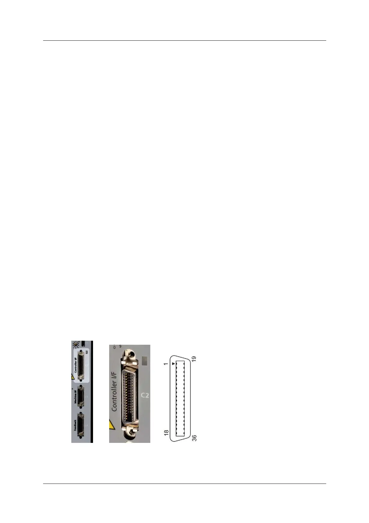
Con troller I / Os – I nterfa ce and Pin Assignm e nt s
Figur e 5 - 6 . Cont roller I / F I nterface
Refer t o the controller interface wiring diagram in Figur e 4- 28.