Drive Setup CDHD
112 User Manual
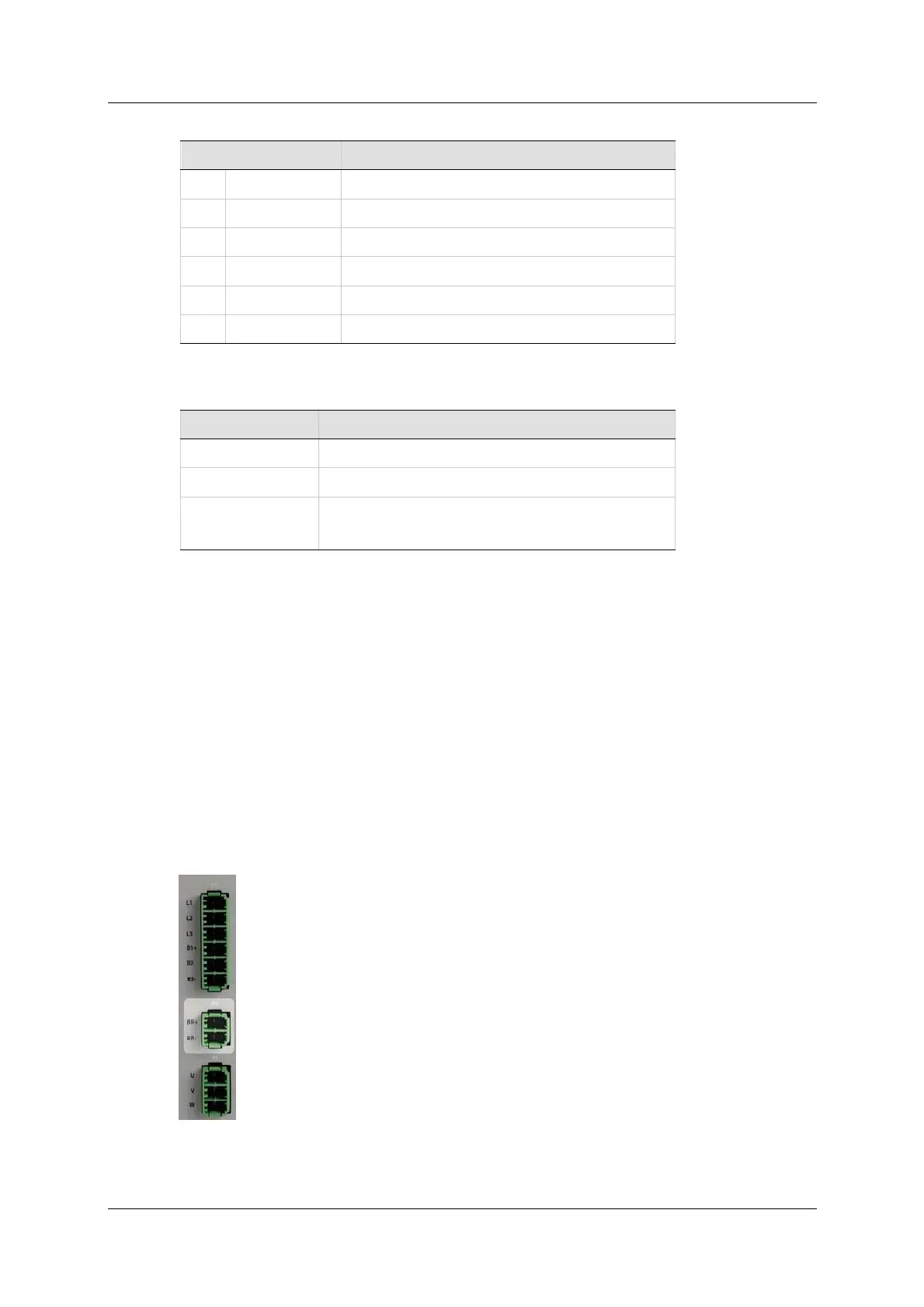
Ta ble 5 - 4 7 . AC I nput a nd Re ge ne rat ion Re sistor I nte r face
Pin Pin La bel Fu nct ion
1 L1 AC Phase 1
2 L2 AC Phase 2
3 L3 AC Phase 3
4 B1+ DC Bus +
5 B2 Regen Bus
6 B3- DC Bus -
Ta ble 5 - 4 8 . AC I nput a nd Re ge ne rat ion Re sistor I nte r face Mating
Connect or
I te m All M odels
Manufacturer Phoenix Con t act
Spring term inal SPC 5/ 6-STCL-7,62 (1718520) (supplied)
Wire gauge CDHD-003/ 006/ 012: 12-14 AWG
CDHD-024/ 030: 10-12 AWG
Connect ing an Ex te r nal Re gene ra t ion Resistor
The CDHD 400/ 480 VAC has an internal resist or capacit y of 300W. For
applications in which regeneration power is expect ed to be greater than 300W,
an external regeneration resist or is required.
Disconnect the internal regeneration resistor wires from terminals B1+ and B2.
Then, connect your own external resistor to B1+ and B2
Recom mended external regeneration resistors are list ed in the section
Regenerat ion Resist ors.
5 .8 .4 M ot or Br ak e
Br a k e uses interface P4 on all CDHD 400/480 VAC m odels.
This is the power output for the electric motor brake system.
Figur e 5 - 2 5 . Brake I nte rface