CDHD Drive Setup
User Manual 113
Ta ble 5 - 4 9 . Br a ke I nte rface
Pin Pin La bel Fu nct ion
1 BR+ Mot or Brake +
2 BR- Motor Brake -
Ta ble 5 - 5 0 . Br ak e I nterfa ce Ma t ing Connector
I te m All M odels
Manufacturer Phoenix Cont act
Spring term inal SPC 5/ 2-STCL-7,62 (1718481) (supplied)
Wire gauge 14-17 AWG
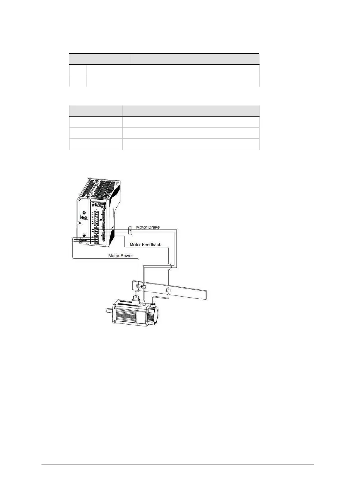
Motor brake wiring is shown in Figure 5-20.
Figur e 5 - 2 6 . M otor Brake W iring - CDHD 4 0 0/ 4 8 0 VAC
Digital Output 7 is dedicated to brake control in all CDHD 400/ 480 VAC m odels.
To m ake the brake output functional, use the ServoStudio Digital I Os screen to
set D igital Ou t put 7 as 2 - Br a ke Release Signal.
Alternately, use the Terminal to define the output function:
output 7 2
Motor Br a ke Fa ults in CD HD 4 0 0 / 4 8 0 VAC
Because of circuit ry differences am ong the CDHD drives, brake faults are
detected differently across the product line.
When the drive detect s a m ot or brake fault, the 7-segm ent display shows n 4 5 ,
and t he m essage FLT 9 8 Pow er Brake Fault is issued.
 Loading...

