Application Setup CDHD
160 User Manual
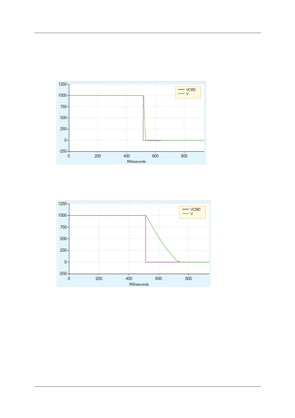
Figure 6-25 shows what happens when Dynamic Braking is engaged. As in the
figure above, the velocity command is set to 0 as soon as the drive is disabled.
However, the actual velocity ramps down as the braking is applied.
Unlike Active Disable, the velocity does not ram p down according to a m otion
profile. The ram p down rate is a function of the m axim um current allowed
(variable ISTOP) and the system inertia and friction.
Figur e 6 - 2 5 . D yna m ic Br ak ing
Figure 6-26 shows Dynamic Braking with a very low value of ISTOP. In this
instance, it takes longer to bring the motor to a stop.
Figur e 6 - 2 6 . D yna m ic Br ak ing w it h Low I STOP Value
I n DI SMODE 4 and DI SMODE 5 both Act ive Disable and Dynam ic Br aking are
supported. In these cases, Active Disable is used t o bring t he mot or to a stop,
and Dynamic Braking is activated after DISTIME.
6 .1 5 M otor Bra k e Control via Relay
The CDHD 120/ 240 VAC models do not have sufficient am perage to activate a
m ot or brake. The CDHD can be connected to a mot or brake via a relay
connected to digital output pins on either the Controller I / F interface or Machine
I / F interface, and configured in Serv oStudio.
Refer to Motor Brake (Optional) and t o the procedure below.
 Loading...

