CDHD Application Setup
User Manual 161
N ote: CDHD 400/480 VAC m odels can also be connected to a m ot or brake via
a relay, and configured in the same manner as 120/ 240 VAC models.
However, direct m otor brake control on 400/ 480 VAC m odels can be
m ore easily implem ented through the dedicated connector (P4).
When using t he P4 connection, use the Te r m ina l screen and VarCom
instructions.
By default, the following conditions are in effect:
Output is off
Voltage to the
brake is 0V
Brake coil is
disengaged
Motor brake holds the
m ot or shaft
Output is on
Voltage to the
brake 24V
Brake coil is
engaged
Mot or brake releases t he
m ot or shaft
The polarity of the digital output can be altered to m ake the drive electronics
m at ch those of the mot or cont rol circuit.
The CDHD disable tim e is programmable by means of the DI STI ME param eter.
When the drive receives a Disable comm and, it first switches off the brake
output and then waits for the brake disengage tim e before actually becoming
disabled.
The brake engage tim e is not programm able. When the drive receives an Enable
comm and, it simult aneously switches on the brake output and becom es enabled.
The drive needs a m axim um of 1.5 m illiseconds to becom e enabled, while a
brake typically takes tens of milliseconds to disengage.
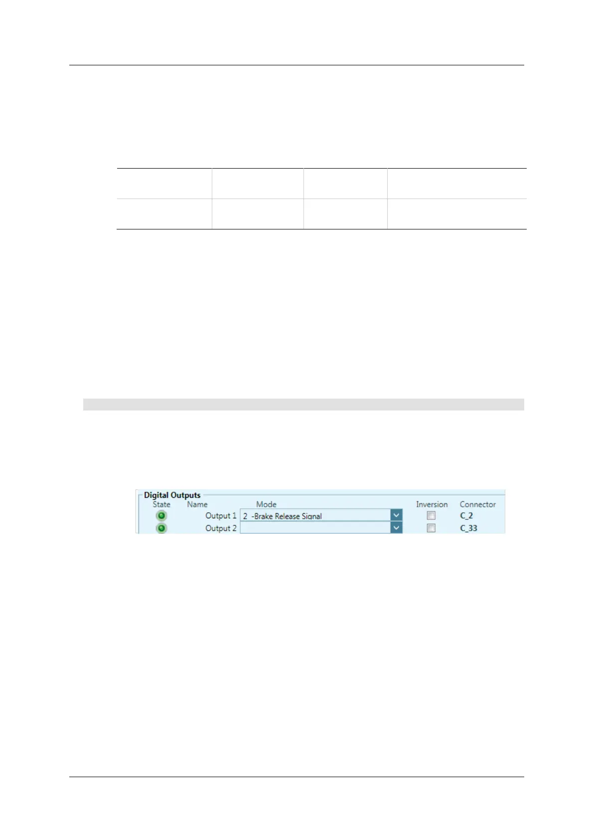
Procedu re - Configur in g Digita l Out put t o Cont rol Br a ke
To configure the digit al output, perform the following procedure in ServoStudio.
1 . Define the output.
Go to the Digital I / Os screen, and set an output (e.g., Output 1) to mode
2 - Bra ke Re lease Signal.
Figure 6 - 2 7 . D igital Out pu t Se ttings for M otor Bra ke Cont r ol
By default:
When CDHD is enabled, the brake output is on.
When CDHD is disabled, the brake output is off.
2 . Go to the Disa ble M ode screen, and set the Active Disable Tim e
(DISTIME). For example, set it to 30 ms.
DI STIME defines the period of tim e after the m otor speed goes below the
Active Disable Speed Threshold (DISSPEED) until the drive is disabled by
the Active Disable function.