Operat ion CDHD
186 User Manual
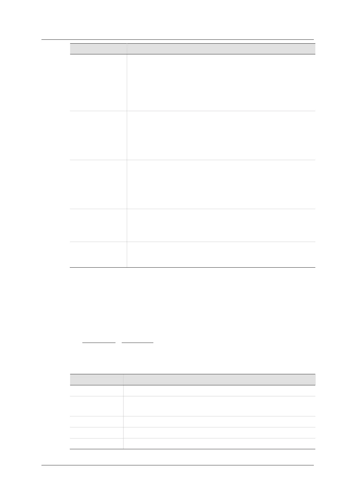
Va rCom D e scription
GEARMODE 0
Encode r Follow e r .
Signals are received on the Controller interface at
pins 28 and 11 (Quadrature A), and pins 9 and 27
(Quadrature B).
Alternately, if inputs 5 and 6 are set to I NMODE 17 and 18,
signals are received from Fast I nputs 5 and 6 on the
Cont roller interface at pins 32 and 15.
GEARMODE 1
Pulse and Dir e ct ion .
Signals are received on the Controller interface at
pins 28 and 11 (Pulse), and pins 9 and 27 (Direction).
Alternately, if inputs 5 and 6 are set to I NMODE 17 and 18,
signals are received from Fast Inputs 5 and 6 on the
Cont roller interface at pins 32 and 15.
GEARMODE 2
Up/ D ow n Count ing.
Signals are received on the Controller interface at
pins 28 and 11 (Up) and pins 9 and 27 (Down).
Alternately, if inputs 5 and 6 are set to I NMODE 17 and 18,
signals are received from Fast I nputs 5 and 6 on the
Cont roller interface at pins 32 and 15.
GEARMODE 3
Encode r follow er ( secondary encoder ) .
Signals are received on the Machine interface at
pins 1 and 11 (Quadrature A) and pins 2 an 12 (Quadrature
B).
GEARMODE 4
Pulse and dir ection ( secondar y encoder) .
Signals are received on the Machine interface at
pins 1 and 11 (Pulse), and pins 2 and 12 (Direction) .
Regardless of the gearing m ode used, the input signal is subject to gearing
calculat ions that allow you t o set the ratio of input pulses t o encoder counts.
Gearing sets up a relationship between the number of input pulses (HWPEXT
counts) and the posit ion increment s of the m otor shaft (or actual m otor position,
PFB). The rate at which position increm ents of the m ot or shaft ( m ot or speed)
occur is determined by the gearing relationship and the line frequency of the
pulse train. The gearing relationship is as follows:
In addition to tuning the current, velocity and position loops, the following are
some of the param et ers used t o configure and m onit or the gearing.
Va rCom Description
GEAR Activat es the gearing function.
GEARI N Numerator of the gearbox equation.
The sign of the GEARI N determines the direction of rotation.
GEAROUT Denom inat or of the gearbox equation.
XENCRES Resolution of the external pulse source.
HWPEXT The posit ion measured by an external feedback device.
 Loading...

