Product Description
FLOWSIC100 · Operating Instructions · 8012513/YSA5/V2-1/2016-07 · © SICK Engineering GmbH 35
Subject to change without notice
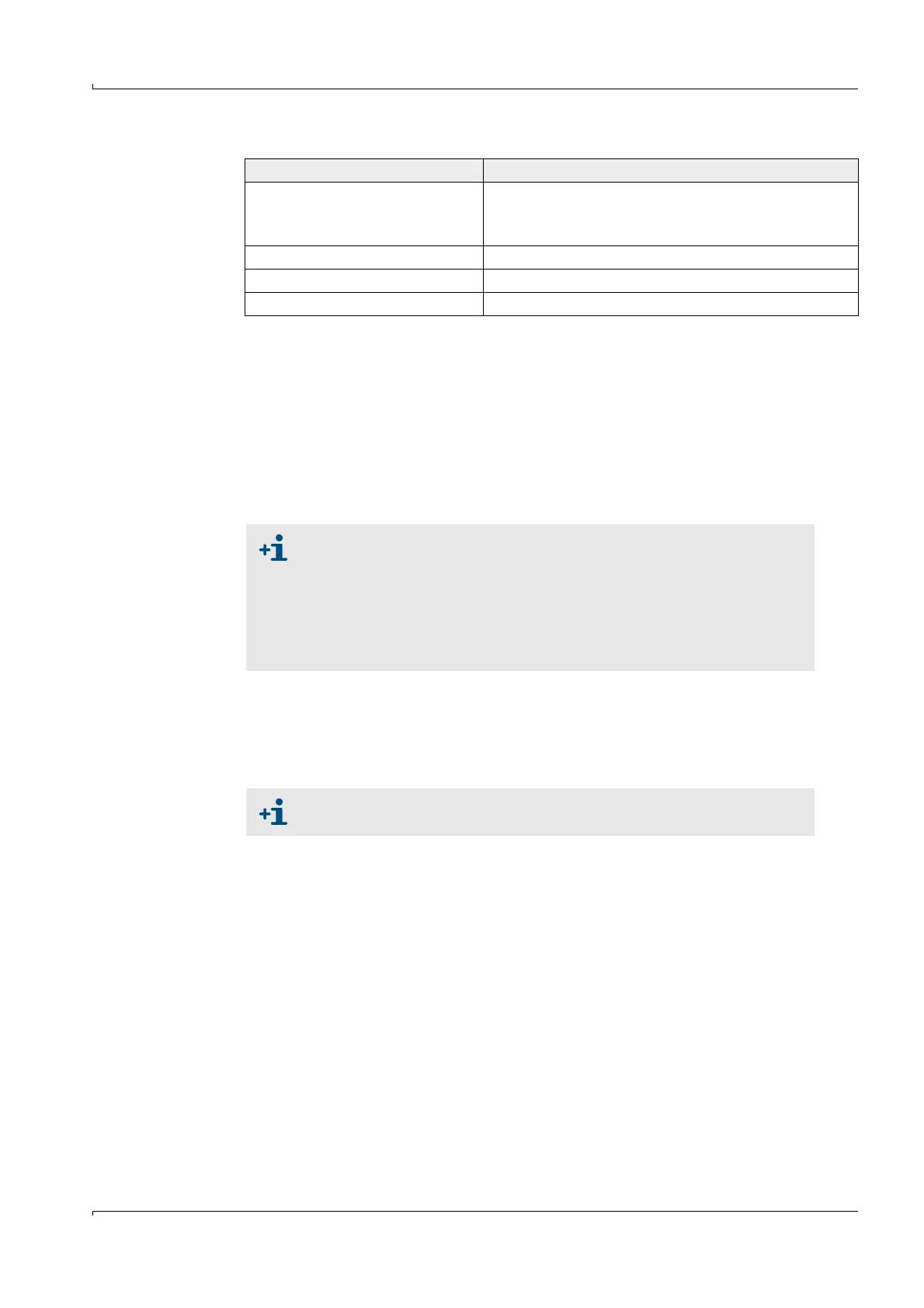
Control buttons
The following functions are additionally available in the display module:
–Entering parameters for start-up
– Initiating a check cycle
– Switching to Maintenance mode.
2 I/O module
For installation on module carriers, communication via I²C bus, or in rack (MCU in 19”
enclosure), selectable as:
– 2x analog output 0/4 ... 22 mA to output further measured variables (load 500
)
– 2x analog input 0/4 ... 22 mA to read in values from external sensors
3 Interface module
Modules to pass measured values, system status and service information to higher
level control systems, optional for Profibus DP, Ethernet and Modbus, for insertion in
slot (
p. 36, Fig. 21).
Button Function
Meas
● Selects the single measured value to be displayed
● Toggles between text display and graphical display
● Displays the contrast settings (after 2.5 s)
Arrows ● Selects next/previous measured value screen
Status ● Displays alarm or error messages
Menu ● Display of main menu
● One module carrier is necessary for each module (to insert on top
hat rail). One module carrier has to be connected to the processor
board with a special cable, other module carriers can be docked to
it.
● Maximum for installation and use:
–2 optional AO modules
–1 optional AI module
Profibus DP-V0 for transfers via RS485 according to DIN 19245 Part 3 as
well as IEC 6115