34 FLOWSIC100 · Operating Instructions · 8012513/YSA5/V2-1/2016-07 · © SICK Engineering GmbH
Product Description
Subject to change without notice
Options
Using the following options, the functionality of the MCU can be extended considerably:
1 Display module
Module to display measured values and status information of the connected sensors
using control buttons (capacitive sensors). The integration of this module into already
delivered control units can only be done by the supplier.
Displays
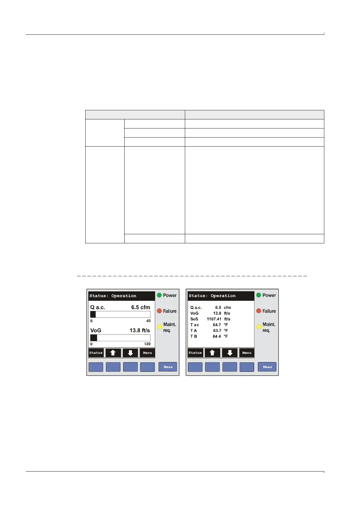
The measurement screen displays bar graphs of two selectable main measured values
of a connected sensor or of the MCU. Alternatively, up to 8 individual measured values
of a sensor can be displayed (switching with button “Meas”).
Fig. 20 LC-Display in graphical display (left) and in text display (right)
If a limit value is exceeded, the display alternates between the measured value and an
alarm message.
Type Display
LED
Power (green) Voltage supply OK
Failure (red) Functional failure
Maint. request (yellow) Maintenance request
LC-Display
Graphical display
(main display)
Two of a variety of possible measured values:
Volume flow in operating state (Q a.c.)
Volume flow in standard state (Q std.)
Gas flow rate (VoG)
Sound velocity (SoS)
Acoustic temperature (T ac)
Transducer temperature A (T A)
Transducer temperature B (T B)
Signal to noise ratio A (SNR A)
Signal to noise ratio B (SNR B)
Mass flow
Text display 6 possible measured values (see graphical display)