Assembly and Installation
FLOWSIC100 · Operating Instructions · 8012513/YSA5/V2-1/2016-07 · © SICK Engineering GmbH 77
Subject to change without notice
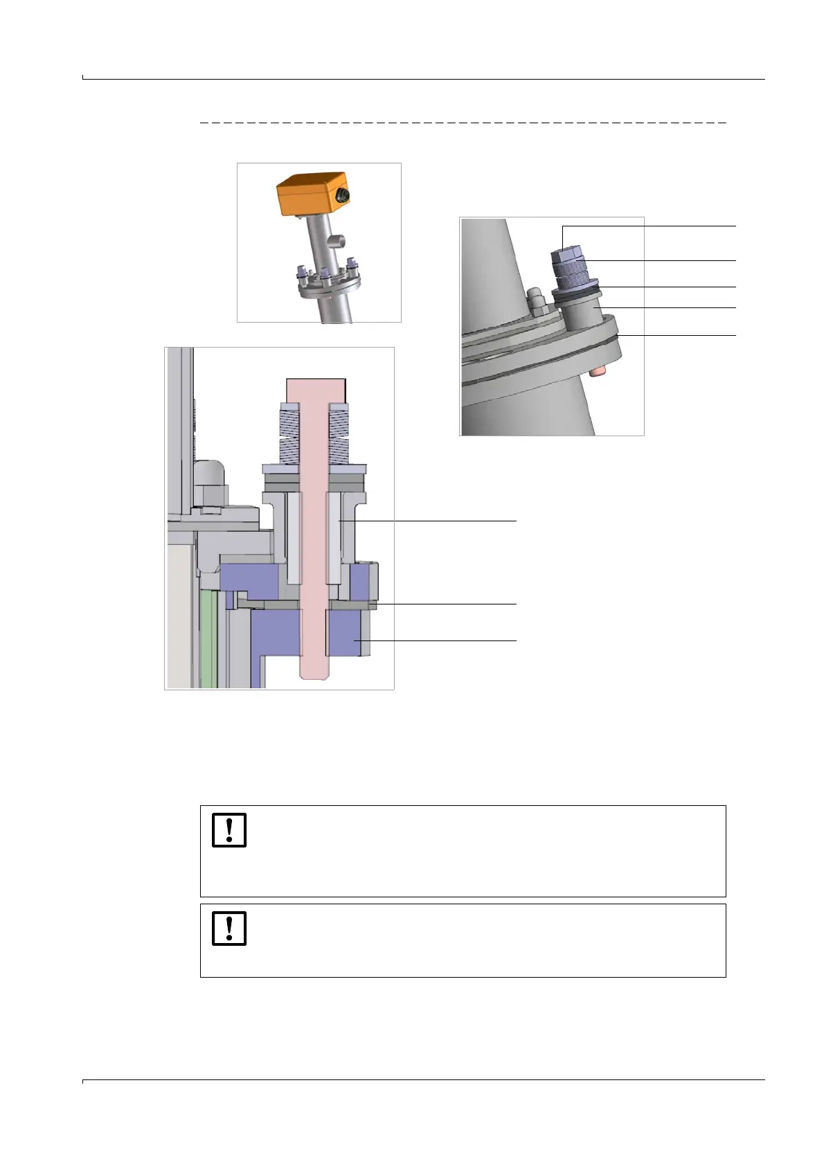
Fig. 48 Installing the assembly/damping set
Installation instructions structure-borne noise damping set K100/K75
Position the flange seal between the flange plates
Fit the screws with all delivered parts in the flange (see Fig. 48)
Flange with thread
Flange seal
Seals
Spring washers
Screw
Bushing
Silicone absorber
Flange seal
NOTICE:
Tighten the screws until the gap between the spring washer sets is no lon-
ger visible.
Then loosen the screw by ¼ turn until the gap between the spring washer
sets is visible again to ensure full damping effect.
NOTICE:
The additionally provided flange seal can be installed to increase the damping
effect if high interference signals continue despite using the structure-borne
noise damping set.