86 FLOWSIC100 · Operating Instructions · 8012513/YSA5/V2-1/2016-07 · © SICK Engineering GmbH
Assembly and Installation
Subject to change without notice
Cable specification for the power supply of the external blower unit in connection box
The following demands with regard to wire cross-sectional area and specific resistance
must be considered for the supply cable to ensure the power supply for the external blower
unit.
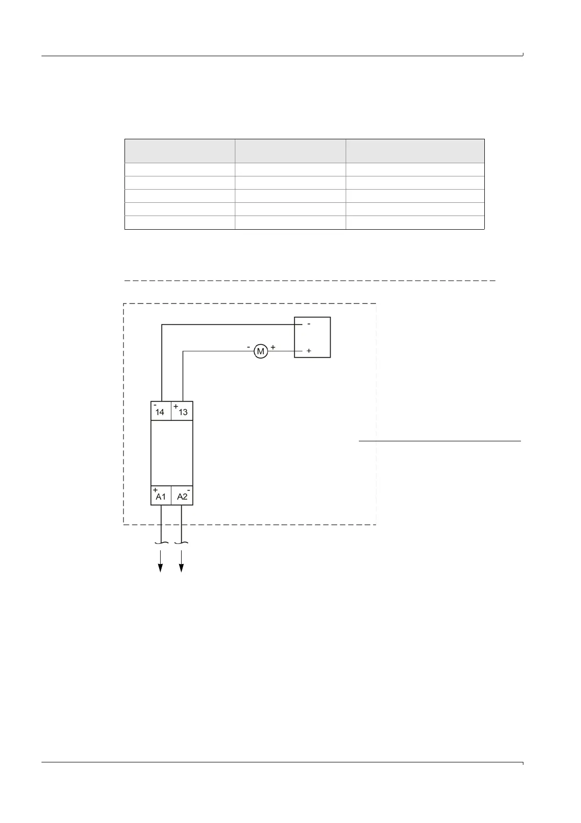
A separate power supply is required for the blower unit for distances greater than 130 m
between the MCU-N and external blower unit. In this case, use the cooling air supply in
connection box with connection 230 V AC.
Fig. 55 Connection of the cooling air control option when using MCU-N 230 V AC with external blower unit 24 V DC
Wire cross-sectional area
mm
2
Specific resistance in
Ω/km
Max. cable length in m
0.5 40 25
0.75 25 40
1.00 18 55
1.5 14 70
2.5 8 130
Internal 24 V DC
power supply of
the MCU for the
blower unit
Solid-state relay
Red
Blower
External blower unit in junction box
To MCU terminal 29 To MCU terminal 15
Grey
Blue
Brown