10
116 | 412
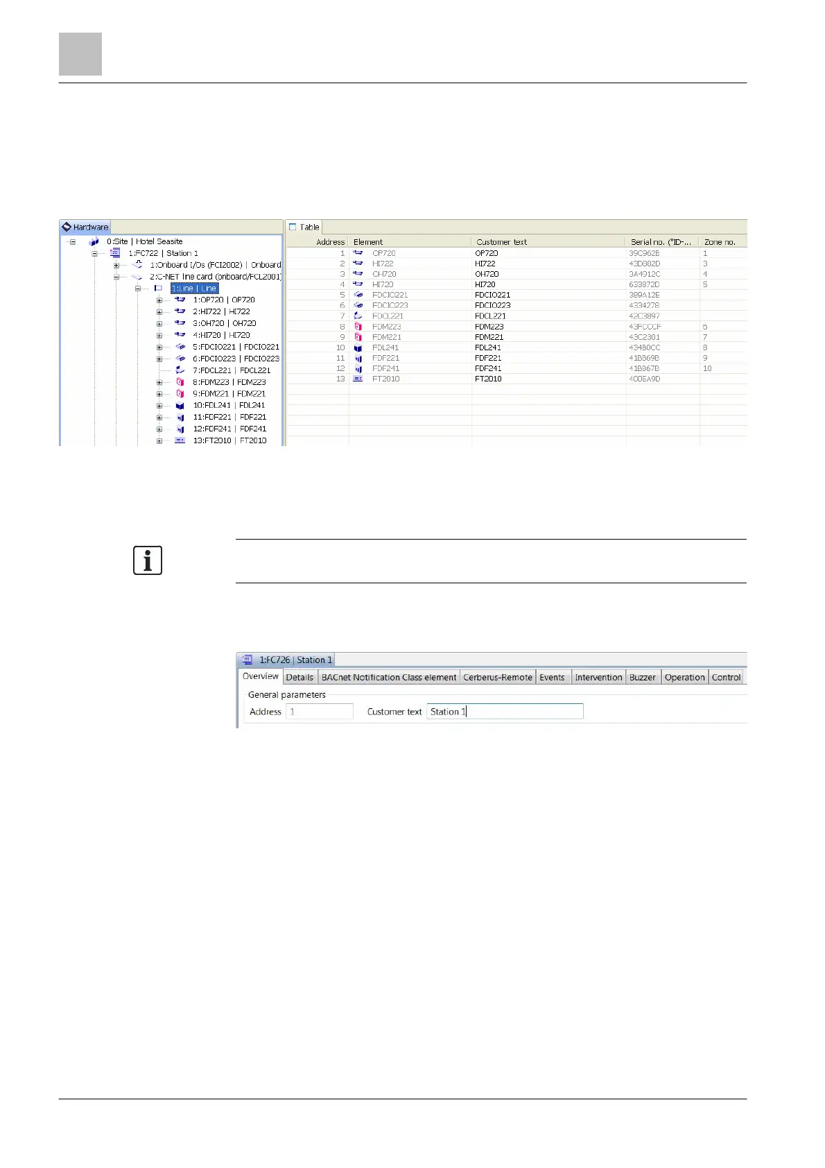
10 'Hardware' task card
The components of the ↑ 'Station' and the peripheral devices are shown in the
'Hardware' task card.
The components are automatically read in when the 'Station' is started.
The C-NET devices must be read in with a command on the 'Station'.
Figure 23: Task card with the tree view and table
Once the data has been loaded into Cerberus-Engineering-Tool, the components
of the 'Station' and the C-NET devices are visible in the 'Hardware tree'.
' can be removed or added if
were not automatically created.
10.1 'Station'
Figure 24: Settings in the detail editor
In the detail editor of the ↑ 'Station', the following properties can be set:
● 'Overview' tab:
– 'Customer text' of 'Station'
● 'Details' tab:
– Stopping the local and global ↑ alarming equipment by means of
'Acknowledge', which is activated by 'Immediate intervention type
'manned''/'Immediate intervention type 'unmanned'' or 'Service intervention
type 'manned''/'Service intervention type 'unmanned''.
– Activation of a message so that the customer is reminded to perform the
maintenance work. 'Maintenance interval [months]' can be set in months.
● 'BACnet Notification Class element' tab, see chapter 'BACnet Notification Class
Element [➙ 338]'.
● 'Cerberus-Remote' tab, see chapter 'Configuring permanent access for
SintesoView'.
● 'Network' tab:
– 'IP address' of the Ethernet port or SAFEDLINK port