LED indicator FTO2002 and mimic display driver FT2001
13
288 | 412
13.5 LED indicator FTO2002 and mimic display driver
FT2001
You will find details on the technical term
' in the chapter 'Glossary'.
The following devices can be used as a mimic display:
● LED indicator FTO2002: For installation in the control panel. This contains 24
LED groups with one red and one yellow LED each.
● Mimic display driver FT2001: It controls up to 48 LEDs that are installed on a
ground plan panel. Communication is via the C-NET.
The mimic display driver has the following inputs and outputs:
– Two control outputs for local buzzer and LED 'SystemOn'
– Two inputs for 'Silence buzzer' and 'START LED test'
There are two elements for creating the mimic display in the 'Operation' task card:
● 'LED ind./mimic 24 LED groups'
With the 'LED ind./mimic 24 LED groups' element, the ↑ visibility of each LED
group (red/yellow) can be configured for a ↑ 'Section' or a ↑ 'Zone'.
● 'LED ind./mimic 48 LEDs'
Each LED can assign any event to the 'LED ind./mimic 48 LEDs' element.
Both elements must be created.
↑ Pre-configuration
To create the mimic display, proceed as follows:
1. Select 'Operation' > ↑ 'Station' in the task card.
2. Create the 'LED ind./mimic 48 LEDs' element, for example, for the 'Station'.
Link [➙ 68]
In a later step once the hardware has been read in and is loaded in Cerberus-
Engineering-Tool, the hardware must still be assigned via the Assign function.
When the hardware has already been read in
To create and assign the mimic display, proceed as follows:
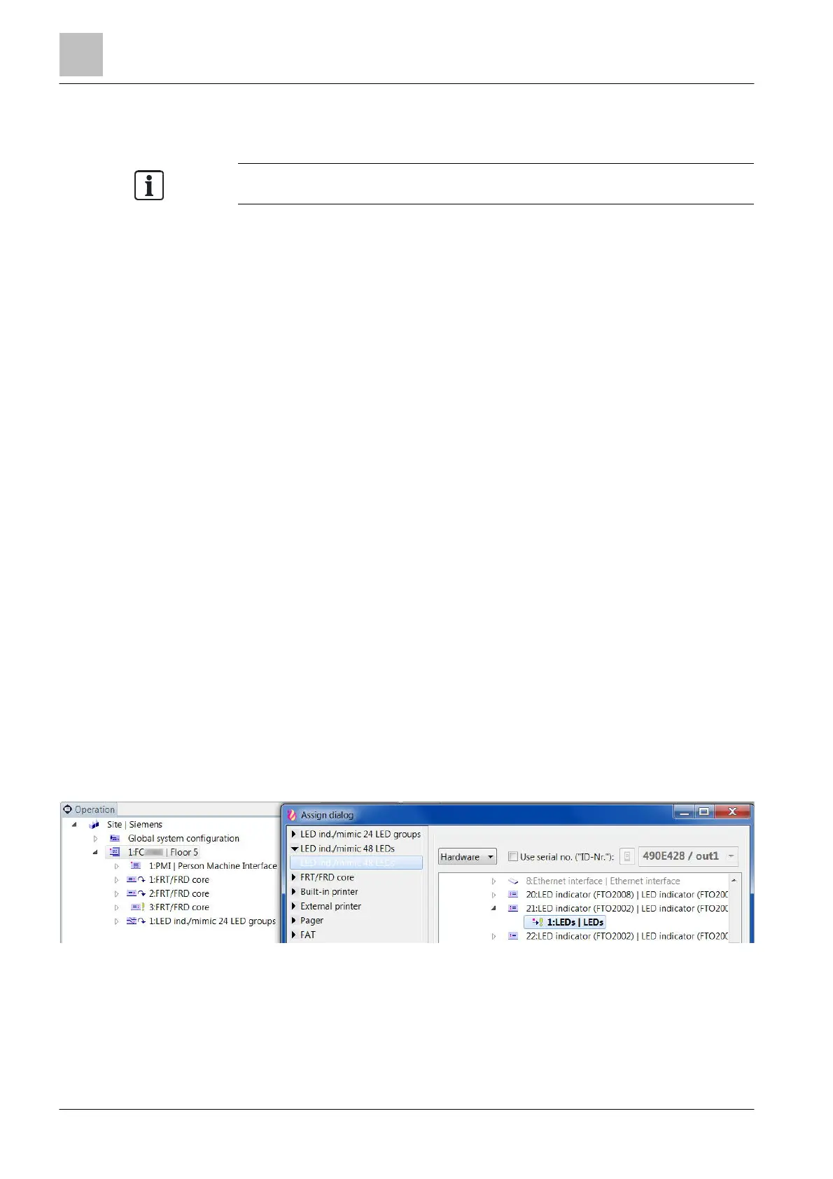
1. Select the 'Operation' task card.
2. Highlight the 'Station' in the tree view.
3. Open the 'Assign dialog' window.
4. Highlight 'LED ind./mimic 48 LEDs', for example.
5. In the ↑ hardware tree, select the corresponding 'LEDs' (LED indicator
FTO2002) or 'LEDs/outputs' (FT2001) element.
6. Click on 'Assign'.
a The mimic display is created and assigned to the hardware.