Troubleshooting
10.3 Test Facilities Graph Screen
FUS1010 IP65 NEMA 4X & IP66 NEMA 7
166 Operating Instructions, 01/2013, A5E02951520-AC
To activate the Test Facilities Graph Screen:
1. In the main menu, scroll to the [Diagnostic Data] menu and select [Test Facilities].
2. Scroll down to [Graph], press the <Right Arrow> and highlight [Yes]. Press <ENTER> to
select.
3. The Test Facilities Graphic Screen will appear on the meter display as shown below.
)
96
>@
'
7Q
G7
6
61
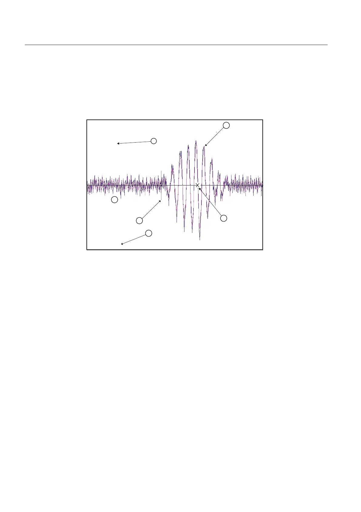
0LQ'DPS
① Damping Factors ④ Min Damping Factor (Hot Key 1)
② ⑤ Digitized Receive Signal TN Marker
③ Crossover Marker ⑥ High Baseline Noise
Figure 10-2 Setting Digital Damping Factor
Setting the Digital Damping Factor to a value HIGHER than the default value of 4 may be
necessary in cases where the signal-to-noise ratio (SN) is found to be unacceptably low
(<15:1), but only if the noise is determined to be asynchronous (i.e., not associated with the
transmit or flow meter timing circuitry) as shown in the signal example above, where the
baseline noise has a higher frequency than the true liquid signal.
The following application conditions may require a higher Digital Damping Factor:
● Close proximity to pressure control valves which may generate in-band acoustic noise
● High un-dissolved gas solids content in liquid.
● High electronic noise from variable frequency drives or other external equipment.