Appendix
A.2 I/O Connections and Wiring
FUS1010 IP65 NEMA 4X & IP66 NEMA 7
188 Operating Instructions, 01/2013, A5E02951520-AC
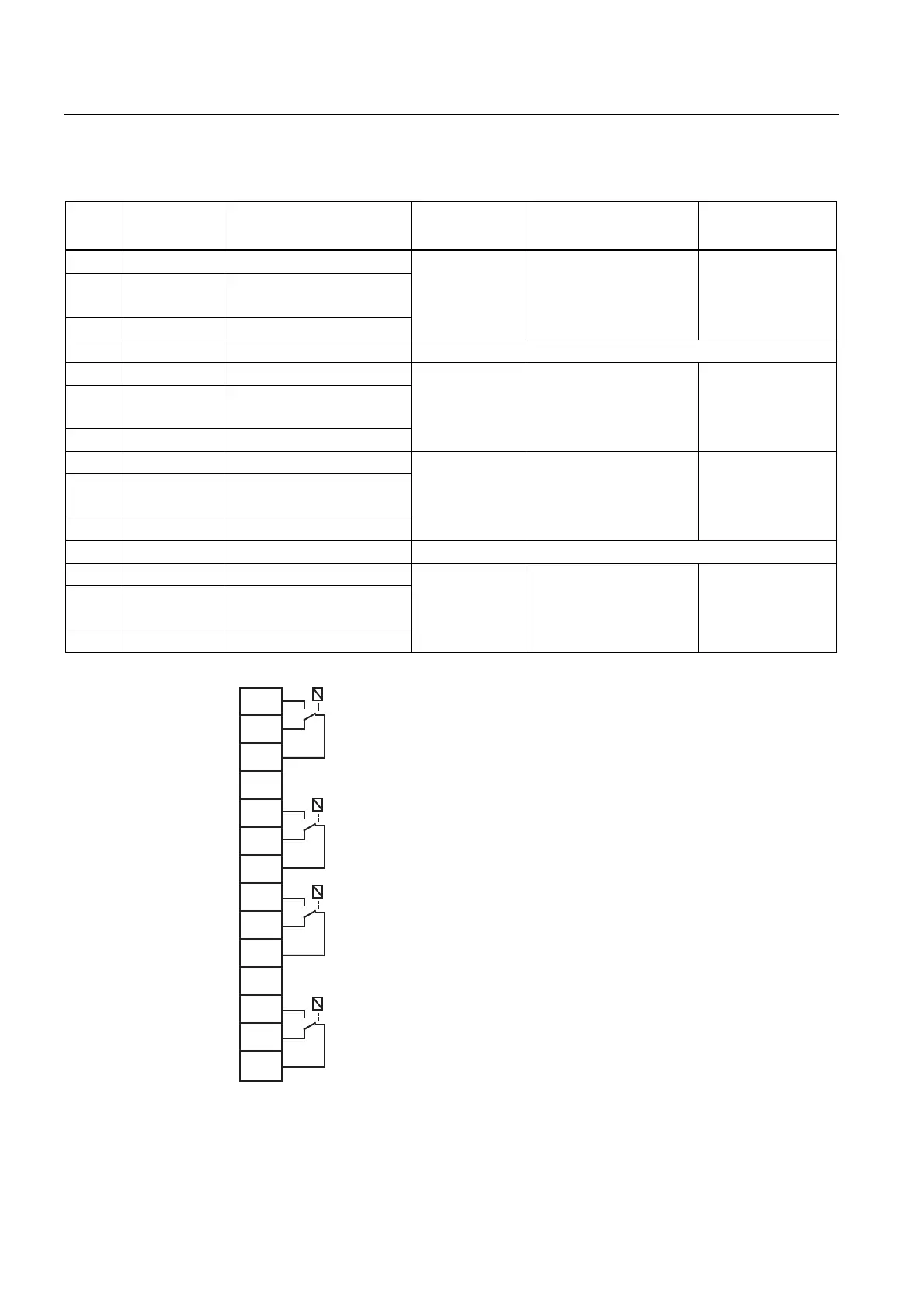
Table A- 6 Input/Output Wiring (TB3) - 7ME39400AL03 and 7ME39400AL04 Expanded I/O Module
Pin# Signal Definition Description Function
Dual Path Only
Function
Quad Path Only
1 K1 A Relay 1 Normally Open
2 K1 B Relay 1 Normally Closed
(7ME39400AL04 only)
3 K1 C Relay 1 Common
Relay 1 Alarm or control functions
set by CH 3
Alarm or control
functions set by
CH5
4 GND Digital Return (GND) DGND
5 K2 A Relay 2 Normally Open
6 K2 B Relay 2 Normally Closed
(7ME39400AL04 only)
7 K2 C Relay 2 Common
Relay 2 Alarm or control functions
set by CH 3
Alarm or control
functions set by
CH5
8 K3 A Relay 3 Normally Open
9 K3 B Relay 3 Normally Closed
(7ME39400AL04 only)
Relay
3 Alarm or control functions
set by CH 3
10 K3 C Relay 3 Common
Alarm or control
functions set by
CH5
11 GND Digital Return (GND) DGND
12 K4 A Relay 4 Normally Open
13 K4 B Relay 4 Normally Closed
(7ME39400AL04 only)
14 K4 C Relay 4 Common
Relay 4 Alarm or control functions
set by CH 3
Alarm or control
functions set by
CH5
1
2
3
4
5
6
7
8
9
10
11
12
13
14
K1-A
GND
GND
*K1-B
K1-C
K2-A
*K2-B
K2-C
K3-A
*K3-B
K3-C
K4-A
*K4-B
K4-C
TB3