Appendix
A.2 I/O Connections and Wiring
FUS1010 IP65 NEMA 4X & IP66 NEMA 7
Operating Instructions, 01/2013, A5E02951520-AC
187
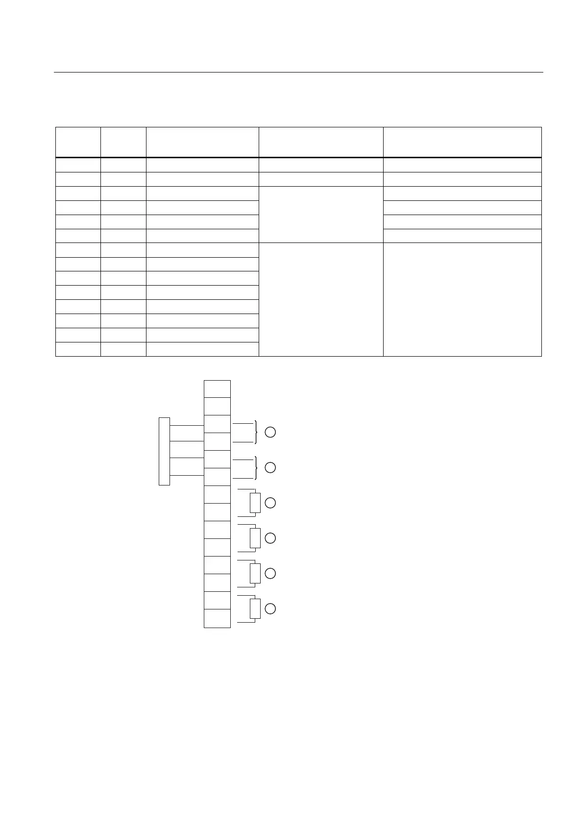
Table A- 5 Input/Output Wiring (TB2) - 7ME39400AL03 and 7ME39400AL04 Expanded I/O Module
Pin# Signal Definition Description Function
Dual/Quad Path Only
14 Chassis Ground Chassis Ground Cable Shield Terminations
13 Chassis Ground Chassis Ground Cable Shield Terminations
12 PG4 GND GND
11 PG3 TTL 5V TTL
10 PG2 GND GND
9 PG1 TTL
0-5000 Hz frequency output ,
assignable
5V TTL
8 Io2 (-) Isolated Return
7 Io2 (+) 4-20mA Output 2
6 Io1 (-) Isolated Return
5 Io1 (+) 4-20mA Output 1
4 Vo2- Ref. Ground
3 Vo2+ 0-10 Volt Output
2 Vo1- Ref. Ground
1 Vo1+ 0-10 Volt Output
Flow meter process variables
assigned to individual outputs
under menu control.
System outputs assignable & scalable
to flow related parameters.
4-20mA outputs also provide a fault
indication by dropping to 2mA if
assigned to flow rate and under fault
conditions.
,R
,R
9R
9R
7%
*1'
*1'
3*
3*
3*
3*
① TB2-11 - POS [+] Total OC ④ 4-20mA Load 1k ohm (max)
TB2-12 - POS [+] Total TTL
② TB2-9 - NEG [-] Total OC ⑤ 0-10V Load 10k ohm (min)
TB2-10 - NEG [-] Total TTL
③ 4-20mA Load 1k ohm (max) ⑥ 0-10V Load 10k ohm (min)