Connecting
5.2 Transmitter Wiring
FUS1010 IP65 NEMA 4X & IP66 NEMA 7
40 Operating Instructions, 01/2013, A5E02951520-AC
',6$%/(
(1$%/(
.(<3$'
6,(0(16
1
$&32:(56833/<
+]
6,1*/(3+$6(
92/76
5(029(&29(5)25
$&&(667232:(5
&211(&7,216$)7(5
(;7(51$/32:(5,6
',6$%/('
&$87,21
+,*+92/7$*(
32:(5
)86(
ಯ9
86(63(&,),(')86(
8/&6$&(57,),('
5$7,1*
$7<3(02/
$7<3(02 /
&RORU&RGHV
+RW
1HX
*1'
86$
%.
:+
*51
(8
%5 %/
<*51
-
$&'&
+27
1(8
*1'*1'
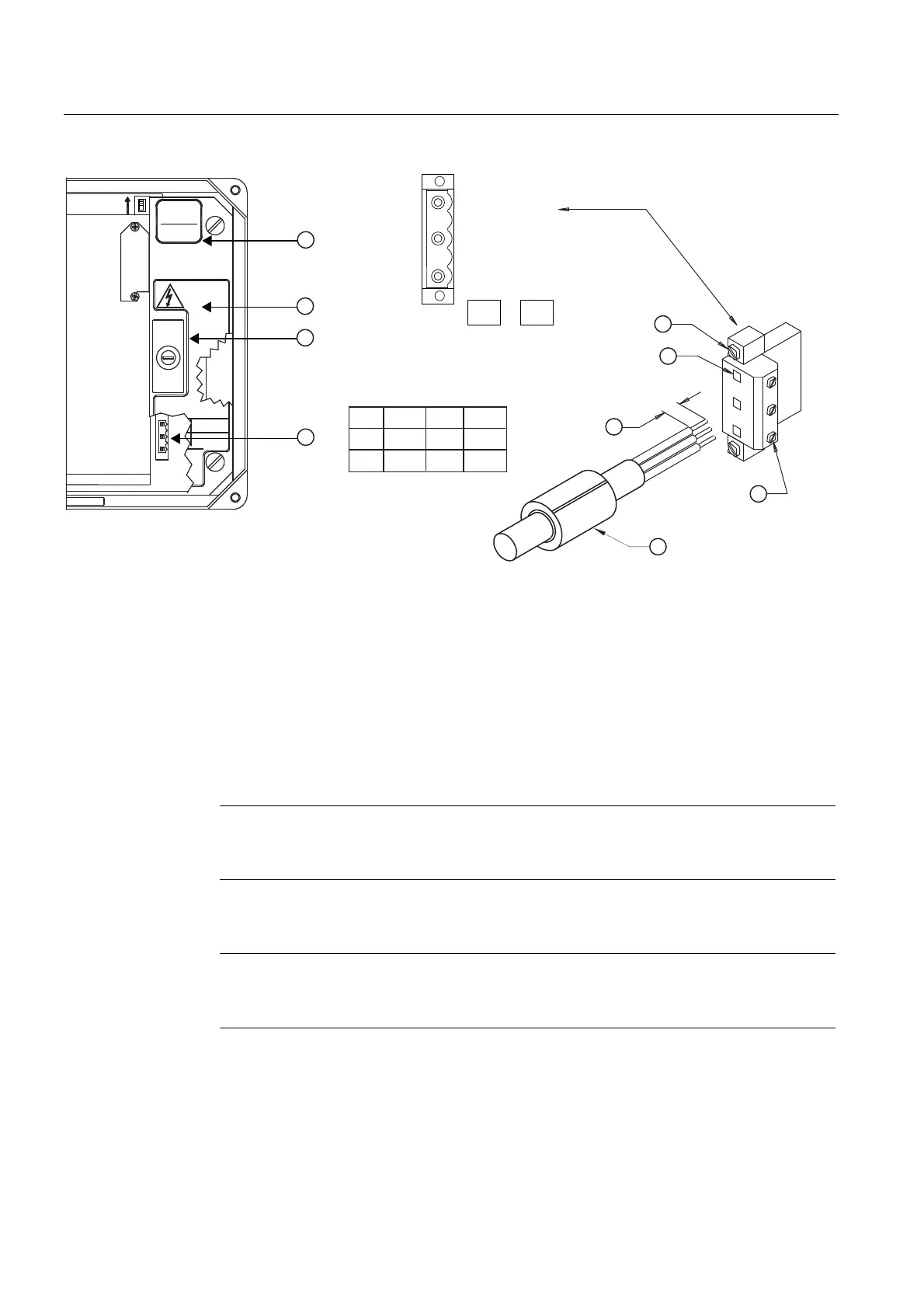
① ⑥ Power Supply Wire Entry
② Power Supply Access Cover ⑦ Strip length 8mm (0.31 in)
③ Fuse F1 ⑧ Wire Clamp Screws
④ Input Power Conn. J10 ⑨ Ferrite power cord
⑤ Connector mounting screws
Figure 5-1 Input Power Plug (J10) Wiring
4. Pull the desired length of input power wires through a cable gland and into transmitter
case before wiring connector.
5. Wire input power connector for AC or DC power depending on power supply provided.
Note
Dress cables and make sure cable length is not excessive as to impede proper
replacement of access cover.
6. Insert wires into wire entry holes and secure by tightening wire clamp screws (see figure
above).
Note
Power Supply connector wires should be stripped AWG 12 - 18 stranded wire or solid
conductors.
7. Plug input power plug into connector J10 and secure using two captive connector
mounting screws.