Connecting
5.2 Transmitter Wiring
FUS1010 IP65 NEMA 4X & IP66 NEMA 7
Operating Instructions, 01/2013, A5E02951520-AC
41
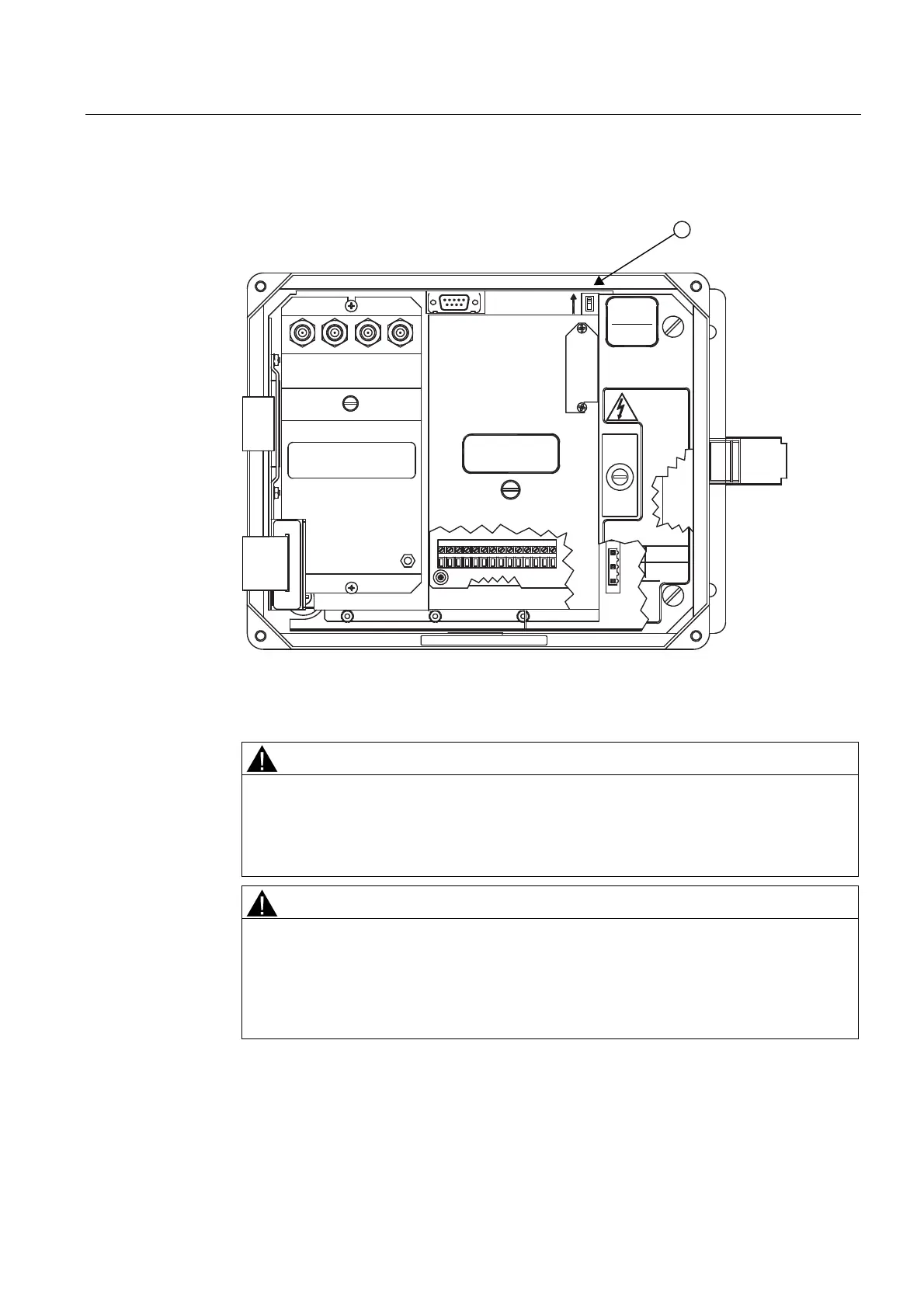
8. Replace access cover. Make sure Keypad Enable switch is in the "Enable" position (see
below).
',6$%/(
(1$%/(
.(<3$'
6,(0(16
1
$&32:(56833/<
+]
6,1*/(3+$6(
92/76
5(029(&29(5)25
$&&(667232:(5
&211(&7,216$)7(5
(;7(51$/32:(5,6
',6$%/('
&$87,21
+,*+92/7$*(
32:(5
)86(
ಯ9
86(63(&,),(')86(
8/&6$&(57,),('
5$7,1*
$7<3(02/
$7<3(02/
6<67(0)/2:0(7(5
+$833$8*(1<
83
83'1 '1
&+$11(/
&+$11(/
5(029(&29(5)25$&&(66
72,2:,5,1*7(50,1$/6
'8$/&+$11(/
,138702'8/(
① Keypad Enable Switch
9. If installing a Temperature Sensor board, go to Wiring Temperature Sensor to Transmitter
(Page 43). If not, go to step 10.
CAUTION
Power Supply Damage
Improp
er power connections will damage power supply and may result in serious injury.
Ensure that all AC or DC power supply connections are properly connected to the
appropriate power source (100-250 VAC @ 50/60 Hz or 9-36 VDC).
WARNING
Electrical Shock Hazard
Certain parts inside the device carry dangerous high voltage and may result in electric
shock, or serious personal injury.
The transmitter must be grounded and the top cover closed before applying power to
the device.
10. Connect the power cables to the appropriate power source (90-240 VAC @ 50/60 Hz or
9-36 VDC). Close top cover.
11. Apply power.